
Tools, Types and Applications
PREREQUISITES
- Basic knowledge of chip removal processes
- Basic knowledge of CNC machining
- LEARNING TIME: 60 min.
OBJECTIVES
- Learn about the main types of tools
- Learn to select the correct type of tool based on the application
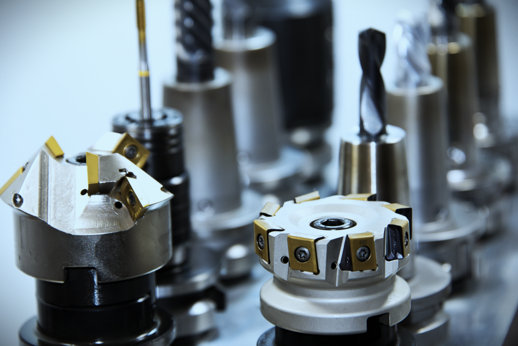
INTRODUCTION
“In workshop technology, a mechanical piece of adequate shape, size and mechanical quality which, used manually or applied to a machine, is used to remove or engrave the material (wood, metals, stones, etc.) of the pieces being worked, or even to impart permanent deformations.” (Treccani.it – Online encyclopedias, Institute of the Italian Encyclopedia).
This is the definition that the Treccani Encyclopedia reports for the term tool. Going into more detail about mechanical processes, this definition is embedded in that of a removal process. It is defined as a process in which a tool, characterized by a relative motion with respect to the surface of the piece, removes a surface layer, transforming the material into chips and generating a new surface.
The macro-category of operations for the removal of chips includes various processes, that are able to obtain different geometries: rotational, prismatic or mixed. The main processes that belong to this macro-category are:
- turning for the creation of axially symmetrical machining operations;
- drilling for making holes;
- milling for prismatic components;
- reaming for finishing cylindrical cavities with tight dimensional tolerances;
- tapping for making threads.
For each type of machining processes (drilling, milling, etc.), operation (face milling, contouring, etc.), working condition (high feed rates, presence of lubricating-coolants, etc.) and material to machine, there are specific tools characterized by different features. In light of such a vast and multifaceted world, it was decided to offer an overview of the most common types of tools in the chip removal sector.
When it comes to tools, the first major distinction that can be made is between:
- Solid Tools
- Indexable Tools
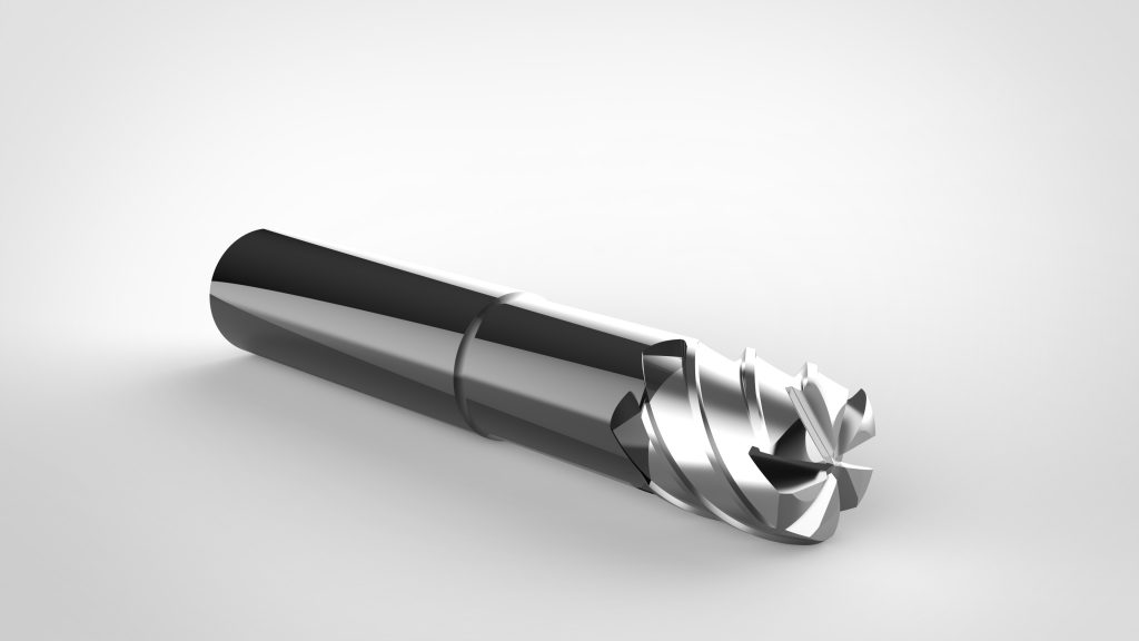
This distinction refers to the structure of the tool itself. As the name suggests, in the first case there is an integral or unique structure between the stem, generally called the shank, and the cutting area.
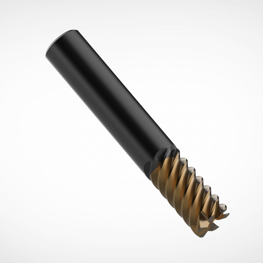
Example of a milling solid tool
Indexable tools, instead have a structure composed of two separate components, namely the stem and the inserts. The stem has a structural function and a seat in which the inserts are then applied, which appear as plates of different shapes, sizes (specified in ISO 1832:2017) and materials and perform the function of removing the machined material.
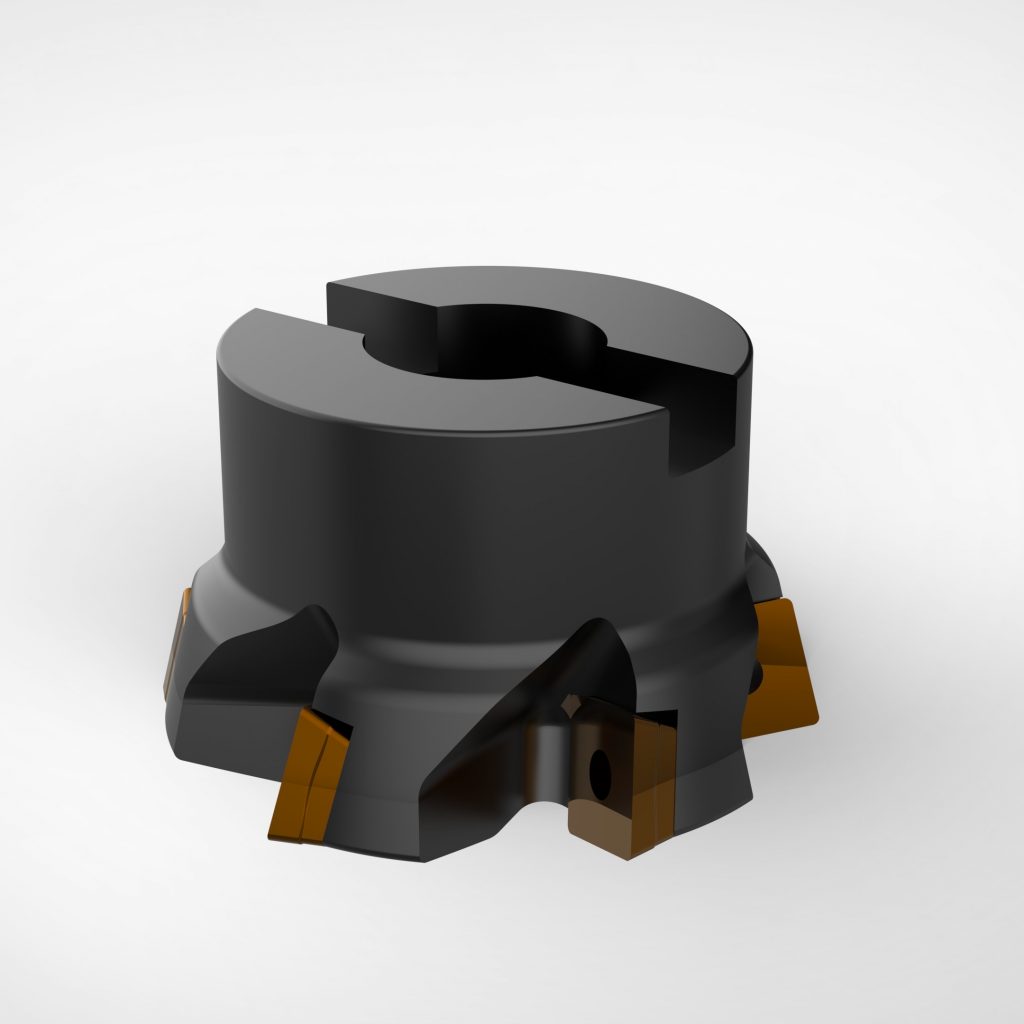
Example of an indexable tool
Both architectures are still widely used in production, the reason being that each of them has pros and cons.
- Solid Tools - Pros
- Integral tools allow you to achieve tight tolerances because their monolithic nature guarantees a dimensional accuracy superior to insert tools.
- Excellent surface finish.
- Solid Tools - Cons
- Since integral tools are made of a single material that is difficult to machine, they are expensive to produce both in terms of process and raw material, which places an upper limit on the achievable dimensions.
- Indexable Tools - Pros
- Indexable tools offer the possibility of reaching dimensions far greater than integral ones.
- Indexable tools allow for more efficient use of cutting material by using it only in the inserts and not for the entire structure.
- They can achieve higher feed rates and consequently a higher material removal rate (MRR).
- Indexable Tools - Cons
- They have a greater source of uncertainty due to the positioning of the insert in its housing, consequently they are not able to obtain tolerances comparable to solid tools.
- Impossibility to reach small diameters because below a certain threshold the fixing of the insert to the stem becomes inefficient if not problematic or even impossible. Generally this threshold is around 12 mm of tool diameter.
- Solid Tools - Pros
SOLID TOOLS
This section describes different types of solid tools:
- Flat-end mill
- Toric-end mill
- Ball-end mill
- Drill bits
- Reamer
- Tapping tool
- Broach
FLAT-END MILL
The flat-end mill is one of the most versatile types of tools available in the milling panorama. There are many types of end mills. The flat one is characterized by a square profile and therefore it has a 90° angle between the side cutting edges that are also the main ones and the surface to machine. Finally, the connection between the two cutting edges has a more or less pronounced chamfer to distribute the cutting forces more effectively and prevent premature wear of the cutting edge at the tip. Thanks to the cylindrical geometry and the presence of cutting edges both along the sides and on the front, it allows material to be removed both in the radial and axial direction and therefore to perform both roughing and finishing operations such as contouring, facing, drilling with a helical strategy and pocketing. The number of cutting edges is variable and can generally range from two to a maximum of eight, but there are also cases with single-edge geometries or even with a number of cutting edges greater than eight, but these remain limited to particular applications.
The number of cutting edges depends mainly on the target material for which the tool is designed and the application. The goal is always to evacuate the maximum volume of chip possible. As for the maximum dimensions, these tools can have diameters of 0.2 mm up to approximately 25 mm, even if there may be exceptions that go beyond these dimensions. Given its versatility, this milling tool is widely used in today's manufacturing industry.
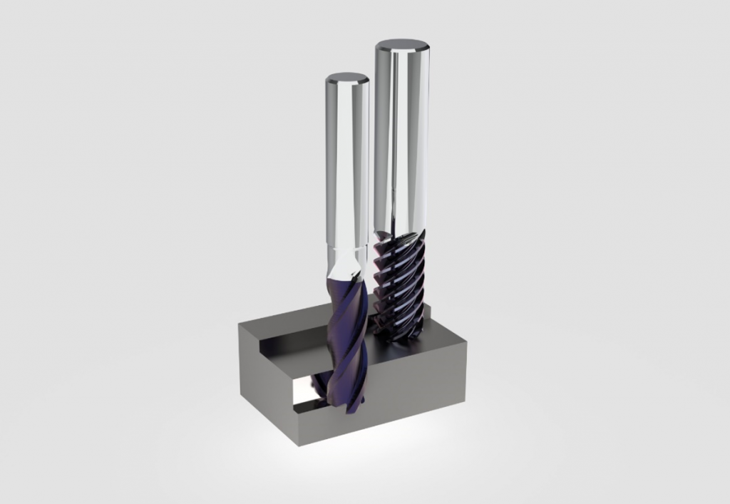
Example of a flat/end mill with two different numbers of cutting edges (3 and 8 cutting edges)
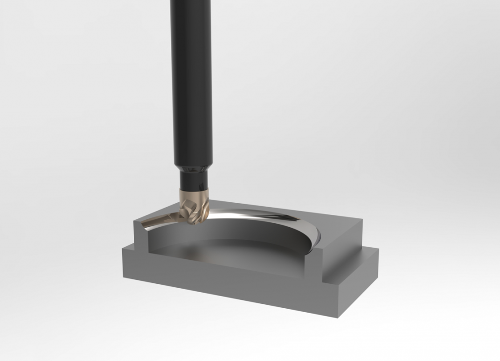
TORIC-END MILL
The toric-end mill is a tool similar both geometrically and from an applicative point of view to the flat-end mill. The main feature that differentiates a toric geometry from the latter is the presence of the radiused edge on the bottom of the tool, which gives the volume swept by the cutting edges the characteristic toric shape. This constructive choice allows to obtain a cutting edge with a section more resistant to the stresses deriving from the cutting allowing greater feeds. Another feature of many toric-end mills is that they have a center-relieved profile, this means that the cutting edge at the bottom of the cutter does not reach the center of rotation,. This is part of the optimization of the cutter since it eliminates the cutting edge portion that removes material at a lower cutting speed. In this case, the tool cannot penetrate the material axially without a pre-hole. The filleted tip geometry is used in the roughing phases of face milling and contouring operations.
Example of a toric-end mill with 4 cutting edges
BALL-END MILL
The ball-end mill has a semi-spherical head with a radius equal to that of the mill itself. As in the previous case, material removal can occur both in the radial and axial directions. Unlike the flat-end mill, there are ball-end mills on the market with fewer cutting edges. Generally the geometries include 2 or 4 cutting edges. Given the versatility of movement in the material and the possibility of orienting the rotation axis more freely and therefore controlling the contact arc (generally the axis is tilted to maximize the cutting speed), this cutter allows you to perform contouring, profiling and copying operations on complex surfaces to machine with other tool geometries (free-form or radiused surfaces).
Example of a ball-end mill
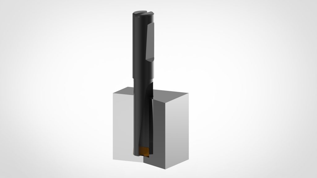
DRILL BIT
As the name suggests, this tool is used for drilling operations. The most commonly used tool geometry is the helical one. This geometry is described as a cylindrical body in which grooves are obtained that have the purpose of facilitating the expulsion of the chip that has formed at the bottom of the hole in the presence of the primary cutting edges. What makes the drill bit specific for this operation is the presence of the primary cutting edges at the bottom and this involves the removal of the material only in the axial direction, allowing the creation of holes with a diameter equal to that of the tool.
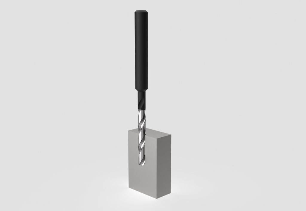
Example of a drill bit
The machining of holes in difficult and/or deep materials requires in-situ lubrication of the cutting edge. This action is necessary for two main reasons:
- Facilitating the evacuation of the chip
- Cooling down the cutting area
To do this, the lubrication cooling fluid can be supplied externally through the external hoses of the machine tool or internally, that is through channels made inside the tool, whose task is to supply the lubrication cooling at the bottom of the feature being machined. In general cases, the drilling tool has two cutting edges but there may be cases with a greater number (3 or 4 cutting edges).
REAMER
The reamer is a tool created for the finishing phase of holes. It has a cylindrical shape at its top create the final diameter, and a conical shape at the bottom to enter in a pre-machined hole and gradually bring it to its final dimension. It has also a chamfered tip to facilitate its insertion into the hole. The cutting edges are slightly inclined respect to the axis of the tool. They are used to create holes in which pins or other components requiring great dimensional and shape precision will then be housed (for example holes with H7 tolerance).
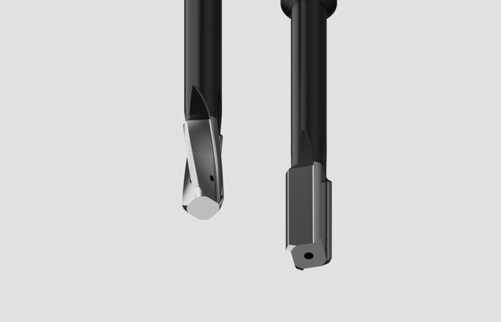
Example of two reamers with inclined and straight cutting edges
BROACH
The broach is a tool used to create internal or external profiles of particular geometries with high precision. Generally the tool is made up of a stem populated in the longitudinal direction by teeth that progressively increase in size until they reach the section that must have the designated profile.
The first major and most general distinction that can be made in the broach family is between traction and compression broaches.
- In the first case, traction means that the force required to cut the material is applied downstream of the working profile.
- In the second case, compression means that the force is applied upstream
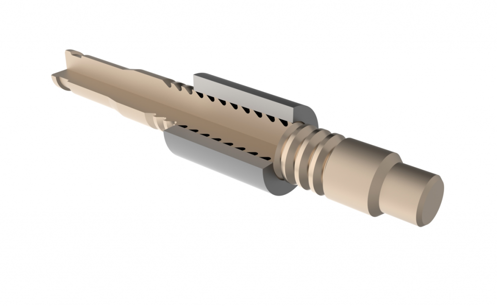
Example of a compression broach
The point at which the feed force is applied to the tool inevitably affects the geometry of the tool itself. A compression broach, in fact, will be shorter than a tensile one because the longer the broach, the greater the risk of instability and compression deformations (buckling).
INDEXABLE TOOLS
Insert tools are a more recent invention. In fact, the first tools of this type began to appear in the industrial sector only in the 1960s. The most commonly used tools in the industry are:
- Contouring mills
- Face milling tools
- Copy and profiling milling tools
- Slot milling tools
- High feed milling tools
- Drill bits
CONTOURING MILLING TOOL
A contouring mill is a cutter capable of creating a plane and simultaneously machining a shoulder. The basic concept is the same as flat end mills in that two surfaces perpendicular to each other are being machined.
Given the contouring process, in fact, it is possible to select a tool that has a more or less long cutting edge and an adequate diameter depending on the feature to machine:
- When machining shallow shoulders, it is possible to use cutters with a diameter greater than the shoulder thickness to obtain a minimum relative radial engagement and to be able to complete the machining in a single pass and still guarantee excellent precision on the perpendicularity of the faces created.
Example of a contour mill
- When machining a deep shoulder, the cutter geometry is characterized by a longer vertical cutting edge.
Example of a high shoulder edge cutter (hedgehog cutter)
- For shoulders characterized by a very wide horizontal plane and a relatively low height, it is possible to opt for a disc mill that allows for a large radial cutting depth with the drawback of accessing only limited axial cutting depths.
FACE MILLING TOOL
A face milling tool is a cutter capable of obtaining a planar machined surface in a direction perpendicular to the axis of rotation. This type of cutter is among the most used in heavy manufacturing. Given its widespread use, over time the geometry of this tool has diversified, adapting to the most diverse process needs. In general, the application of face milling cutters can be divided into three subcategories, namely:
- General face milling (characterized by geometries that allow both roughing and finishing)
- High feed (characterized by cutting edge geometries that allow high feed rates and consequently high MRR)
- Finishing (with wiper inserts)
One of the main aspects that characterizes a face milling cutter is the entering angle of the cutting edge. In fact it is the factor that mostly influences the directions of the cutting forces on the cutting edge, impacting the stability of the machining.
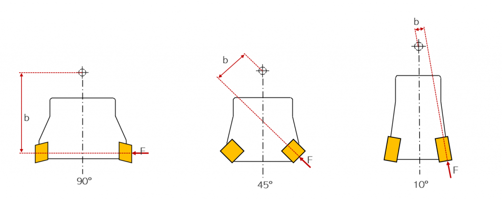
Scheme of face milling cutters with decreasing entering angle
In general, a low lead angle allows for much more stable machining compared to other configurations. The radial force in this case is almost null, minimizing tool deflection. For this reason, the mill can be long, as in the case of milling the bottom of a deep pocket. The main disadvantage is the reduced depth of cut.
Example of a face milling cutter with a mid entering angle
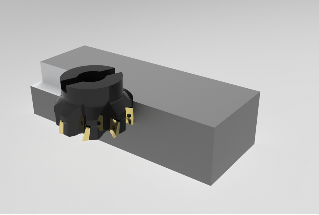
On the contrary, a cutter with a 90° entry angle has less stability in terms of cutting dynamics because the forces generated are mainly radial and therefore affect stability. The main advantage of this tool is its versatility, because it allows greater axial penetrations and can also be used for other operations such as contouring.
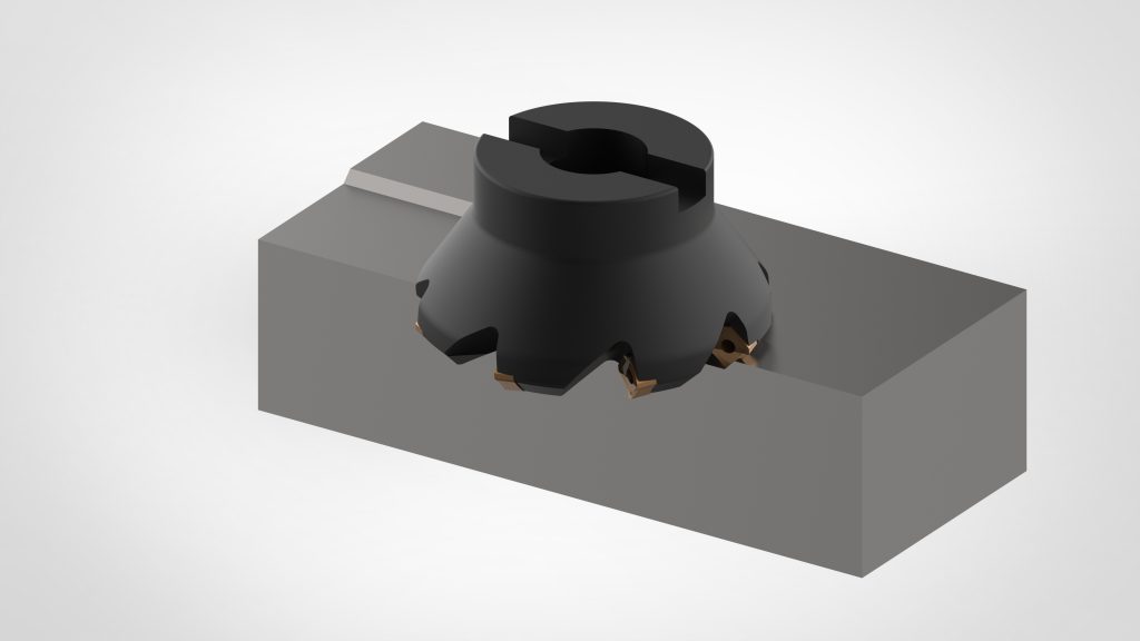
Example of a face milling cutter with high entering angle
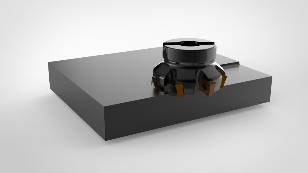
In addition to inserts with prismatic geometry, there are inserts with round geometry or with very big radii. The adoption of this geometry helps to obtain a more robust cutting edge and also a variable chip thickness depending on the axial depth of cut. In fact, by maintaining a reduced penetration compared to the radius of the insert, the chip thickness remains low despite a high feed rate, while by maintaining a penetration comparable to the radius, sustainable feed rates are lower since the chip thickness increases.
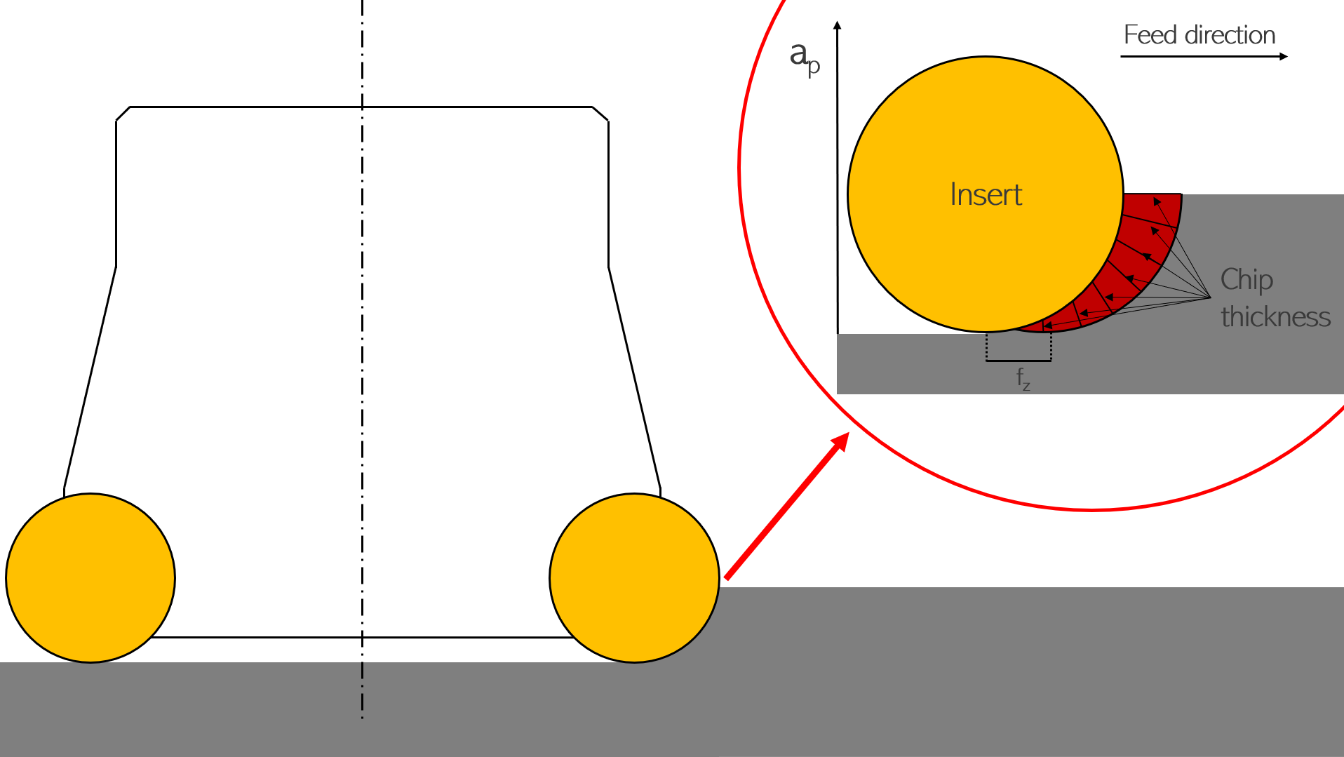
Schematic of a face milling cutter with circular inserts showing increasing chip thickness with increasing axial engagement
Finally, in finishing processes, the use of cutters with wiper inserts is favored. This geometry is characterized by 2 cutting edges, the main one with a registration angle ranging from 25° to 90° and the secondary one with a registration angle of 0°, i.e. parallel to the machined surface. The function of the second cutting edge is to avoid the formation of crests that form on the surface of a milled component due to the passage of the inserts.
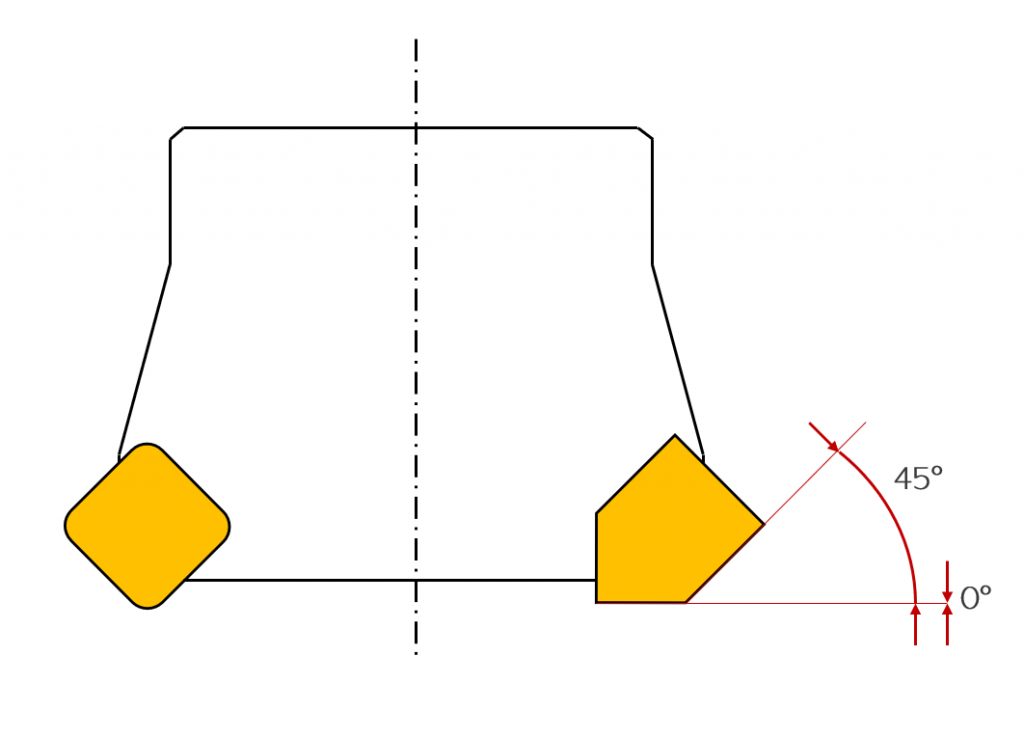
Example of a wiper insert with two cutting edges at 0° and 45° respectively
PROFILING AND COPYING MILLS
A profiling cutter is a mill capable of machining concave and convex geometries with an inclined axis. For this type of geometries without sharp edges or small radii/fillets, the machining process is divided into three main steps:
- Roughing
- Semifinishing
- Finishing
In this type of operation, the profiling insert cutter is mostly used in roughing and semi-finishing operations, while for finishing operations, ball-end solid mill are more often used.
Indexable mills designed for profiling and copying are characterized by large round or radiused inserts. The reason why this type of tool is selected for the first two machining steps is that the material removal rate is high and therefore it is necessary to satisfy requirements for stability and considerable feed rates per tooth.
The two main geometries adopted for profiling and copying operations are of two types:
- Round inserts, where the shape of the tool body is similar to that of face milling/contouring, but the applied inserts are circular. This geometry is often optimized for roughing phases as the shape of the round insert allows for a more robust cutting edge and better distribution of cutting pressures.
- Ball-head, where the geometry is more slender. In this case, the diameter of the cutter can be smaller thanks to the oblong shape of the inserts. This configuration is preferred in the roughing/semi-finishing phase.
Example of profile cutters with shaped and round inserts
SLOT AND CUTTING MILLS
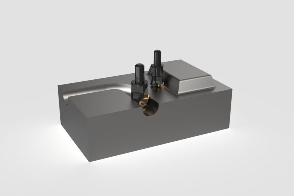
A groove cutter is a tool capable of removing solid material and generating grooves within the material of various sizes and aspect ratios (between the width and height of the groove itself). For this type of operation, 2 types of cutters are mainly chosen: disc cutters and end mill cutters. Disc cutters can also be used as parting tools.
- Disc cutters are cutters with a high radial to axial dimension ratio. Their shape and working principle are very similar to those of a circular saw. The inserts are mounted on the radial ends of the disc. This geometry allows for obtaining grooves as wide as the axial dimension of the inserts. Thanks to the large diameter of the tool, it is not necessary to have high rotation speeds on the spindle as the cutting speed is guaranteed by the diameter of the cutter. This type of tool can be used to cut off sections and create open straight grooves (starting from the outside of the piece).
Example of an insert disc cutter
The biggest limitations introduced are the forced linearity of the grooves and the difficult evacuation of the chip. Despite the disadvantages, however, this configuration allows for high stability in machining, high productivity and the creation of grooves of different widths since inserts of different thickness can be used with the same cutter.
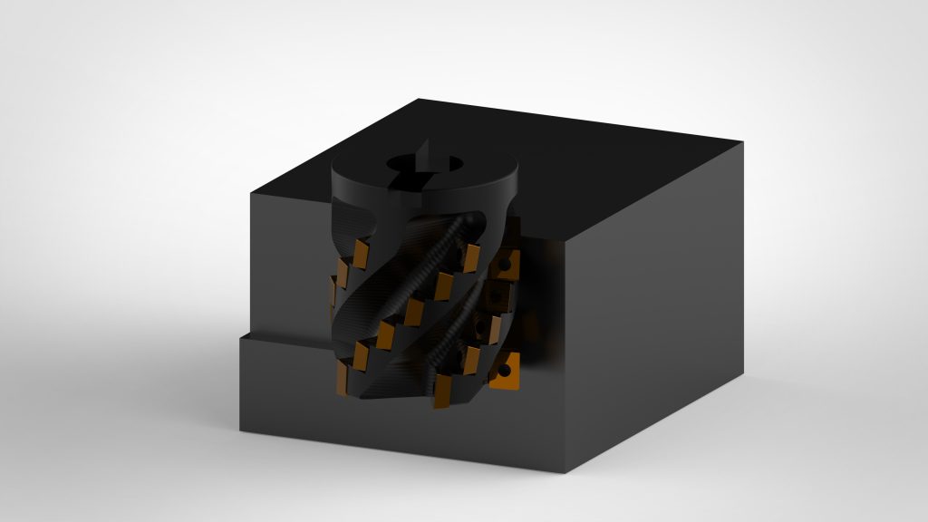
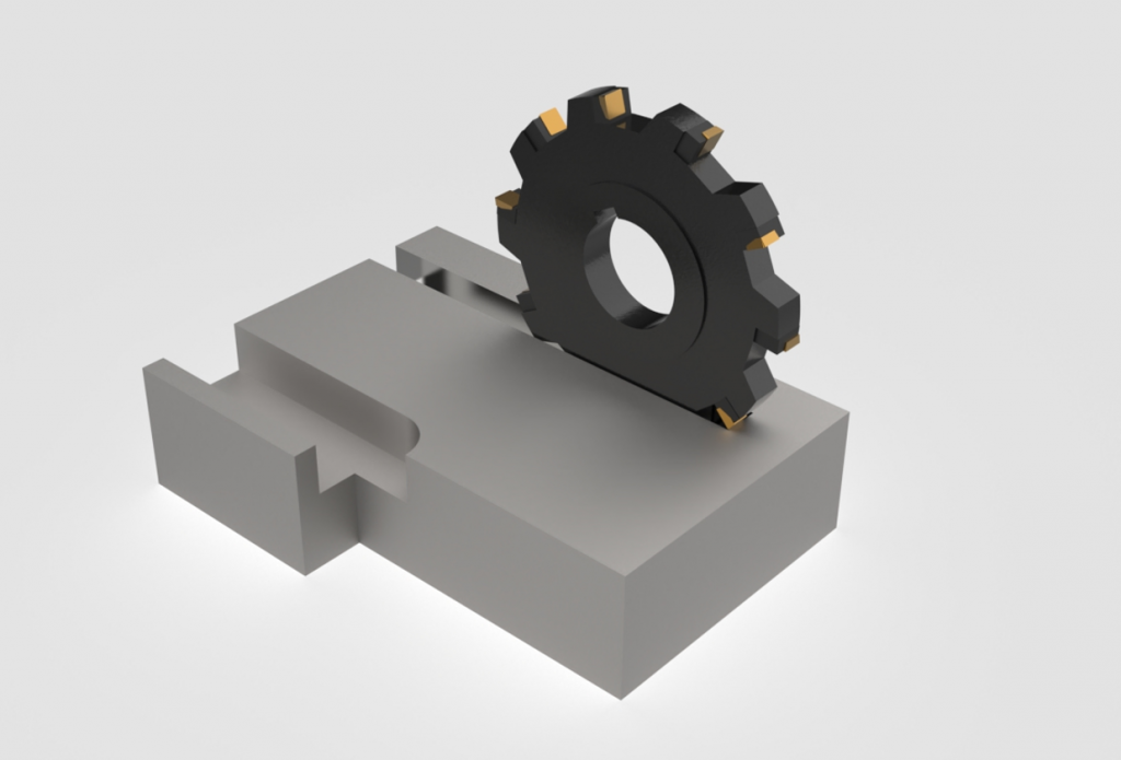
- The end mill is a classic face milling cutter with cutting edges on both the head and the side. These cutters are capable of removing material in both the axial and radial directions. The cutters used have a geometry suitable for face milling and contouring (with the relevant cutting diameter limits).
Example of a end mill for slotting
The main advantages given by the adoption of this tool are the possibility of making straight, curved or even angled grooves and the possibility of making closed slots (plunge entry or in pre-drilled material). The main disadvantages instead are the high forces generated, the limit on the reachable depth and the greater susceptibility to vibrations (less stability in the machining).
HIGH-FEED MILLING TOOLS
High feed milling intrinsically corresponds to a high productivity operation. This type of tool has been designed to achieve high MMR (Material Removal Rate) values. These cutters can generally be either solid or insert-type, but the latter are the ones that allow working at more extreme speeds. The working conditions of these tools correspond to a high feed rate coupled with a reduced depth of cut. These parameters allow for an optimized chip section because, by reducing the depth of cut and increasing the feed, it is possible to generate cutting forces directed more towards the Z axis (towards the spindle) rather than in the radial direction, a much more problematic direction for the tool. Adopting this strategy ensures greater process stability and a consequent extension of the tool life.
Example of a high feed milling cutter
The application of this concept can be done on many types of cutters but mainly on face milling cutters. The morphology can vary a lot especially based on the material and dimensions. For example, the number of cutting edges can vary from 4 to 14. The reason for having so many teeth on a single mill is that it allows for a high feed per revolution and it has more engaged teeth even at low radial depth of cut. This configuration is very effective when large surfaces need to be face milled and a lot of material removed. With the same initial outlay (due to the quantity of inserts needed for the tooling) there is a gain in productivity (high MRR) and the consumption of the inserts decreases.
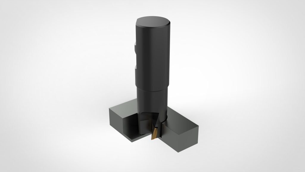
INDEXABLE DRILLS
The indexable drills have the same function as the integral ones but, when compared, they have different advantages.
As far as the general structure of the tool is concerned, what is most important is its ability to create working conditions less affected by vibrations and chatter phenomena. This naturally leads to more precise machining and a better surface finish. Also in this case, lubrication cooling is important and having a body of a more easily machinable material which is steel in he case of indexable drills, helps to obtain more efficient internal liquid supply channels and to have a better irrigation of the cutting area, allowing an even higher material removal rate.
Example of an indexable drill
The advantages enjoyed by insert drill bits are mainly two:
- First of all, as with milling cutters, they allow for reaching dimensions larger than integral ones both due to the more economical construction and due to the structural limitations presented by a body entirely in hard metal, but they in turn have a minimum size limit.
- They require a more expensive initial outlay than a solid tip but in the long run the initial cost is amortized since only the worn inserts need to be replaced and not the entire tool.
- ACQUIRED SKILLS
Hai conseguito le seguenti competenze:
- Learn about the main types of tools
- Learn to select the correct type of tool based on the application

USEFUL CONTACTS, LINKS AND DOWNLOADS
Contacts
- For students:
Prof. Annoni Massimiliano, Politecnico di Milano: massimiliano.annoni@polimi.it - For educators:
Prof. Annoni Massimiliano, Politecnico di Milano: massimiliano.annoni@polimi.it - For companies:
Prof. Annoni Massimiliano, Politecnico di Milano: massimiliano.annoni@polimi.it