Calcoli alla mano...
Utilizzo della curva coppia e potenza del mandrino per la scelta dei parametri di taglio
PREREQUISITES
- Basic knowledge of CNC
- Basic knowledge of milling processes
- Basic knowledge of CAD/CAM software
- LEARNING TIME: 60 min.
OBJECTIVES
- Choose the appropriate tool diameter and rotational speed for the machining considering the torque and power that can be delivered by the spindle
- Perform useful calculations to define the cutting parameters as a function of the chosen position in the spindle characteristic curve
IL CASO DI STUDIO
In questa lezione verrà affrontato il un caso di fresatura di una tasca che presenta dei raccordi di raggio pari a 1,5 mm.
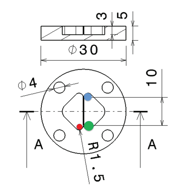
-
- Dc1 = 2 mm
- Dc2 = 2,8 mm
- Dc3 = 4 mm
-
- Materiale del pezzo:
-
-
- Acciaio da bonifica, C40 (Carbonio: 0.4%)
- Durezza Brinell: 204 HB
- k_\mathrm{c1} = 1800 N/mm2; x = 0,25
- Avanzamento al dente raccomandato (per tutte le frese): 0,01 mm < f_\mathrm{z} < 0,03 mm
- Profondità di taglio raccomandata: a_\mathrm{e} <0,4 D_\mathrm{c}
- Velocità di taglio raccomandata: v_\mathrm{c} = 126 m/min
- Profondità di taglio assiale raccomandata: a_\mathrm{p} = 0,5 mm
-

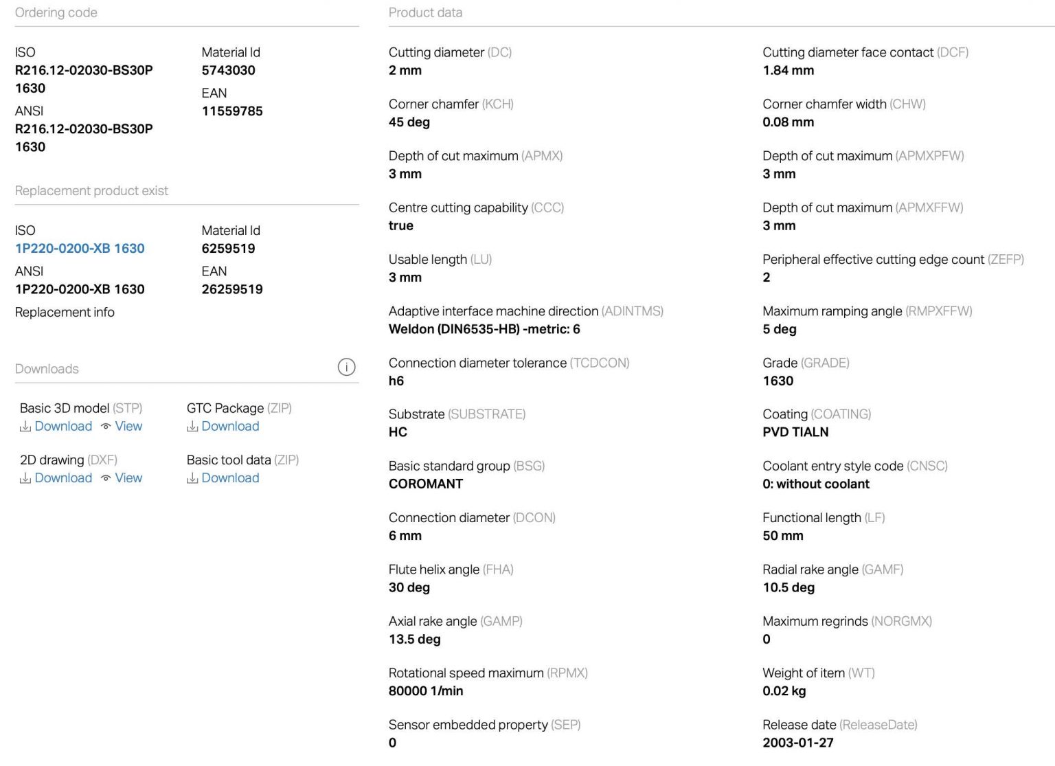
- R216.12-02030-BS30P, qualità GC 1630
- Angolo di spoglia frontale: \gamma_0 = 10°30’; \kappa_\mathrm{re} = 90°
- Si raccomanda la fresatura in concordanza
Tutte e tre le frese hanno:
- Lo stesso \gamma_0, \kappa_\mathrm{re} e Z = 2 (numero di denti)
- La stessa lunghezza a sbalzo = 6 mm
- Lo stesso materiale (E = 600 GPa)
DOMANDE
- Quali diametri dell’utensile possono eseguire la lavorazione e perché? Si fornisca la spiegazione per le scelte fatte
- Calcolate la forza di taglio per le frese adatte dopo aver scelto il corretto f_\mathrm{z}!
- Calcolate la deflessione utensile per le frese adatte alla lavorazione
CALCOLO DI FORZE E MOMENTI
v_\mathrm{c}=\frac{\pi \cdot D_\mathrm{c} \cdot n}{1000} \rightarrow n=\frac{1000 \cdot v_\mathrm{c}}{\pi \cdot D_\mathrm{c}}
D_\mathrm{{c1}} = 2\;\mathrm{mm}
n=\frac{1000 \cdot 126}{\pi \cdot 2} = 20063\;\mathrm{rpm}
D_\mathrm{{c2}} = 2,8 \;\mathrm{mm}
n=\frac{1000 \cdot126}{\pi \cdot 2,8} = 14331 \;\mathrm{rpm}
v_\mathrm{f}=n \cdot f_\mathrm{z} \cdot Z
\mathrm{\bigg(\dfrac{mm}{min}\bigg)=\bigg(\dfrac{giri}{min}\bigg)\bigg(\dfrac{mm}{giro \cdot dente}\bigg)(-)}
v_\mathrm{{f1,max}} = 20063 \cdot 0,03 \cdot 2 =
= 1204 \;\mathrm{\dfrac{mm}{min}}
v_\mathrm{{f2,max}} = 14331 \cdot 0,03 \cdot 2 =
= 860\;\mathrm{ \dfrac{mm}{min}}
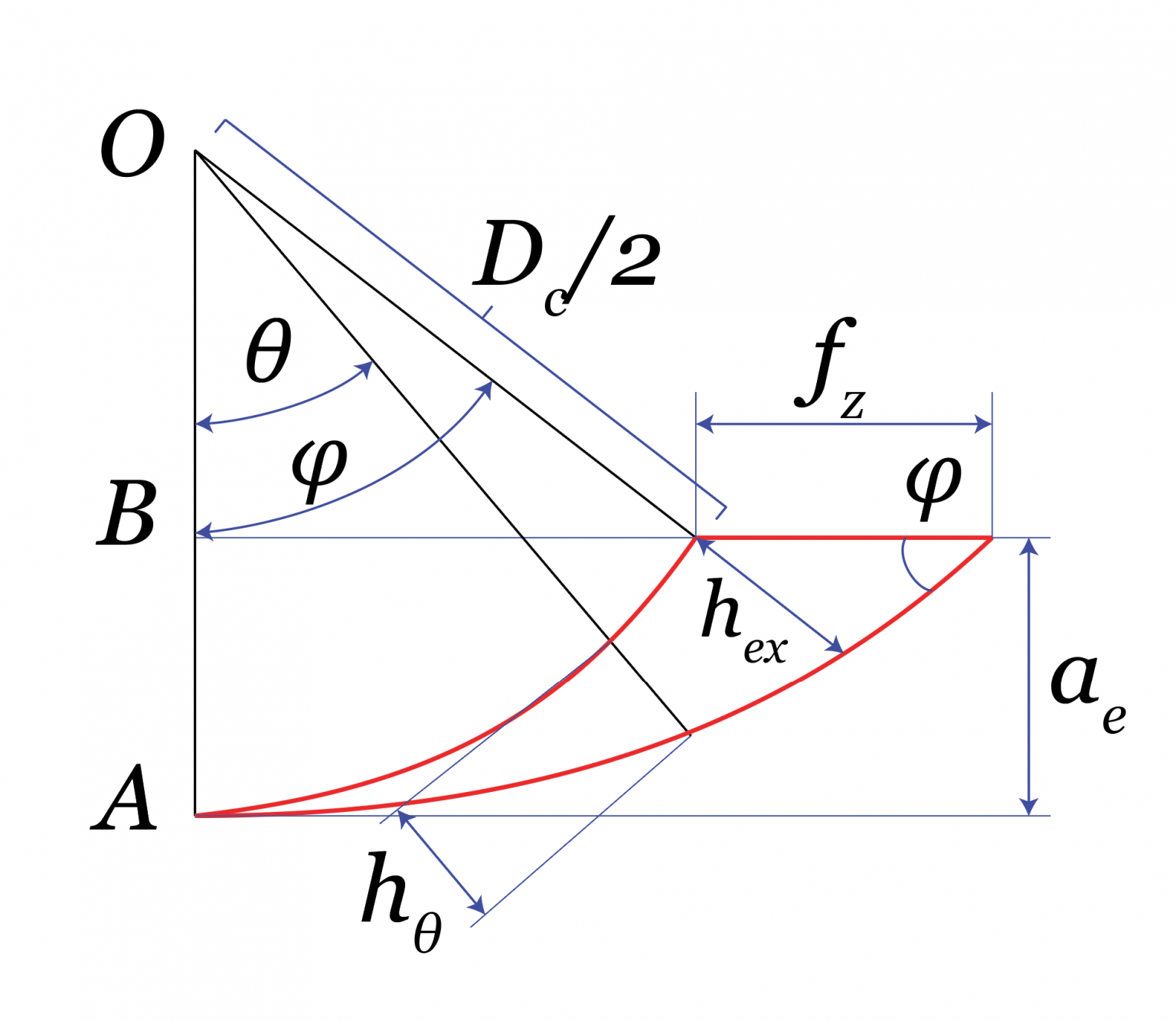
Arco in presa:
cos(\varphi) = 1 – \dfrac{2a_\mathrm{e}}{D_\mathrm{c}}
Con a_\mathrm{e}<0,4D_\mathrm{c} per entrambe le frese.
Usiamo il massimo:
\varphi = arcos \bigg(1-\dfrac{2 \cdot 0,4\cdot D_\mathrm{c}}{D_\mathrm{c}}\bigg) =
= arcos(0,2)=1,37 \;\mathrm{rad}
Attenzione a gradi e radianti!
Uguale per entrambe le frese
Loading..........
The Data is Not Available
Calcoliamo spessore di truciolo e pressione di taglio.
h_\mathrm{ex}=f_\mathrm{z}sen(\varphi)
Dato che \varphi e f_\mathrm{z} sono uguali per le due frese, avremo solo un valore h_\mathrm{ex}.
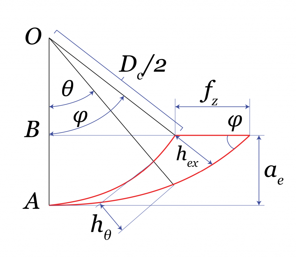
Calcoliamo lo spessore di truciolo massimo nel caso di avanzamento massimo:
h_\mathrm{ex,max}=0,03 \cdot sen(1,37)=0,03 \cdot 0,98 = 0,0294 \simeq 0,029 \;\mathrm{mm}
h_\mathrm{ex,min}=0,01 \cdot sen(1,37)=0,01 \cdot 0,98 = 0,0098 \simeq 0,010 \;\mathrm{mm}
k_\mathrm{c,ex}=\dfrac{k_\mathrm{c1}}{h_\mathrm{ex}^{x}} \bigg(1-\dfrac{\gamma_0}{100} \bigg)

k_\mathrm{c,ex,0,03}=\dfrac{1800}{0,029^{0,25}} \bigg(1-\dfrac{10,5}{100}\bigg)=\dfrac{1800}{0,413}\cdot0,895 = 3901 \;\mathrm{\dfrac{N}{mm^2}}
k_\mathrm{c,ex,0,01}=\dfrac{1800}{0,010^{0,25}}\bigg(1-\dfrac{10,5}{100}\bigg)=\dfrac{1800}{0,316}\cdot0,895 = 5088 \;\mathrm{\dfrac{N}{mm^2}}
Procediamo al calcolo di forza e momento:
F_\mathrm{c,ex}=k_\mathrm{c,ex}\cdot A_\mathrm{D}=k_\mathrm{c,ex}\cdot h_\mathrm{ex} \cdot a_\mathrm{p}
a_\mathrm{p} = 0,5 \;\mathrm{mm} per entrambe le frese.
Dato che abbiamo solo un valore di h_\mathrm{ex} e un solo valore a_\mathrm{p}, abbiamo solo un valore della forza.
F_\mathrm{c,ex,max}=3901\cdot 0,029 \cdot 0,5 = 56,6 \;\mathrm{N}
M_\mathrm{c,ex} = F_\mathrm{c,ex}\dfrac{D_\mathrm{c}}{2}
D_\mathrm{c1} = 2 \;\mathrm{mm}
M_\mathrm{c,ex1,max} = 56,6\dfrac{1}{1000} = 0,057 \;\mathrm{Nm}
D_\mathrm{c2} = 2,8 \;\mathrm{mm}
M_\mathrm{c,ex2,max} = 56,6\dfrac{1,4}{1000} = 0,079 \;\mathrm{Nm}
La potenza richiesta per il taglio ipotizzando un solo dente in presa è:
P_\mathrm{c,ex} = F_\mathrm{c,ex}\cdot v_\mathrm{c}
Considerando che un solo talgiente è impegnato alla volta, possiamo usare semplice formule per calcolare la coppia e la potenza.
P_\mathrm{c,ex,max}= 56,6 \;\mathrm{N} \cdot 126 \;\mathrm{\frac{m}{min}} =56,6 \;\mathrm{N} \cdot \dfrac{126}{60}\;\mathrm{\frac{m}{s}} = 119 \;\mathrm{W}
Loading..........
The Data is Not Available
Attenzione allo spessore di truciolo al valore minimo di f_\mathrm{z} che è troppo piccolo rispetto al tipico raggio dello spigolo tagliente (es. 0,020 mm)(minimum chip thickness effect).
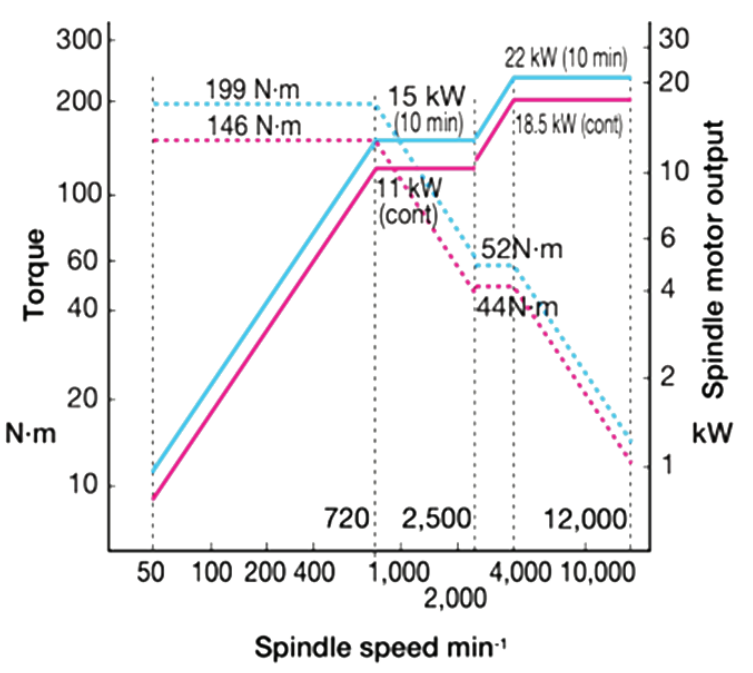
Una volta calcolate coppia e potenza di taglio, è opportuno verificare che il mandrino della macchina possa sopportare i carichi richiesti. Dal manuale Kern Evo:
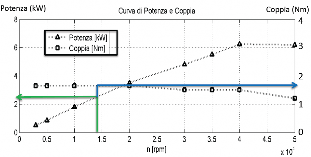
Considerando il caso peggiore (D_\mathrm{c2} = 2,8 \;\mathrm{mm}; f_\mathrm{z} = 0,03 \;\mathrm{mm}; n = 14331 \;\mathrm{rpm}):
M_\mathrm{c,ex2,max} = 0,079 \;\mathrm{Nm}
La coppia disponibile è > 1,5 Nm @ 14331 rpm
P_\mathrm{c,ex,max}= 119 \;\mathrm{W} = 0,119 \;\mathrm{kW}
La potenza disponibile è > 2 kW @ 14331 rpm
COMPENSAZIONE DELLA VELOCITÀ DI AVANZAMENTO IN CURVA

D_\mathrm{c1}=2 \;\mathrm{mm}
v_\mathrm{fm1,max}=20063 \cdot 0.03 \cdot 2 =
= 1204 \;\mathrm{\dfrac{mm}{min}}
D_\mathrm{c2}=2,8 \;\mathrm{mm}
v_\mathrm{fm2,max}=14331 \cdot 0.03 \cdot 2 =
= 860 \;\mathrm{\dfrac{mm}{min}}
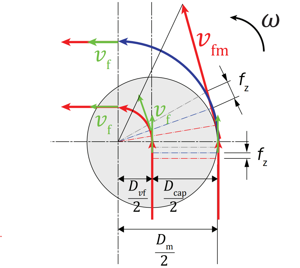
\dfrac{v_\mathrm{fm}}{v_\mathrm{f}}=\dfrac{D_\mathrm{m}}{D_\mathrm{vf}} \rightarrow v_\mathrm{f} = v_\mathrm{fm} \dfrac{D_\mathrm{vf}}{D_\mathrm{m}}
Con: D_\mathrm{vf}=D_\mathrm{m}-D_\mathrm{c}
v_\mathrm{f} = v_\mathrm{fm} \dfrac{D_\mathrm{m}-D_\mathrm{c}}{D_\mathrm{m}} = v_\mathrm{fm} \bigg(1-\dfrac{D_\mathrm{c}}{D_\mathrm{m}}\bigg)
v_\mathrm{f1,max}=1204 \bigg(1-\dfrac{2}{3} \bigg) =
=\dfrac{1204}{3} = 401 \;\mathrm{\dfrac{mm}{min}}
v_\mathrm{f2,max}=860 \bigg(1-\dfrac{2,8}{3}\bigg) =
= 57 \;\mathrm{\dfrac{mm}{min}}
Il centro della fresa più grande deve rallentare molto!
Che cosa accade se non compensiamo la v_\mathrm{f} in curva?
Proviamo a applicare i parametri di taglio raccomandati dal costruttore nel centro della fresa:
v_\mathrm{f} = n \cdot f_\mathrm{z} \cdot Z

D_\mathrm{c1} = 2 \;\mathrm{mm}
v_\mathrm{f1,max} = 20063 \cdot 0,03 \cdot 2 =
=1204 \;\mathrm{\dfrac{mm}{min}}
D_\mathrm{c2} = 2,8 \;\mathrm{mm}
v_\mathrm{f2,max} = 14331 \cdot 0,03 \cdot 2 =
=860 \;\mathrm{\dfrac{mm}{min}}
\dfrac{v_\mathrm{fm}}{v_\mathrm{f}}=\dfrac{D_\mathrm{m}}{D_\mathrm{vf}} \rightarrow v_\mathrm{fm} = v_\mathrm{f} \dfrac{D_\mathrm{m}}{D_\mathrm{vf}} \rightarrow v_\mathrm{fm} = v_\mathrm{f} \dfrac{D_\mathrm{m}}{D_\mathrm{m}-D_\mathrm{c}}
Con D_\mathrm{vf} = D_\mathrm{m}-D_\mathrm{c}
v_\mathrm{fm1,max} = 1204 \cdot \dfrac{3}{3-2} =
=1204 \cdot 3 = 3612\;\mathrm{\dfrac{mm}{min}}
v_\mathrm{fm2,max} = 860 \cdot \dfrac{3}{3-2,8} =
=860 \cdot 15 = 12900 \;\mathrm{\dfrac{mm}{min}}
ATTENZIONE!
f_\mathrm{z,eff} = \dfrac{v_\mathrm{fm}}{n\cdot Z}
f_\mathrm{z,eff1,max} = \dfrac{3612}{20063 \cdot 2} =
= 0,090 \;\mathrm{mm}
Tre volte il massimo consentito!
f_\mathrm{z,eff2,max} = \dfrac{12900}{14331 \cdot 2} =
= 0,45 \;\mathrm{mm}
ATTENZIONE!
Loading..........
The Data is Not Available
- Solo l’utensile più piccolo rimane all’interno dei valori consigliati di avanzamento; negli altri tre casi l’utensile può essere danneggiato dalle forze di taglio
- Spessori di truciolo maggiori corrispondono a valori inferiori di pressione di taglio
- …ma spessori di truciolo maggiori corrispondono a forze maggiori; la forze cambia ordine di grandezza per la fresa grande
Spessore di truciolo massimo:
h_\mathrm{ex} = f_\mathrm{z}sen(\varphi) = f_\mathrm{z}sen(1,37) = f_\mathrm{z}\cdot 0,98
D_\mathrm{c1} = 2 \;\mathrm{mm }
h_\mathrm{ex1,max} = f_\mathrm{z,eff1,max}\cdot 0,98 =
= 0,090 \cdot 0,98 = 0,088 \;\mathrm{mm}
D_\mathrm{c2} = 2,8 \;\mathrm{mm}
h_\mathrm{ex2,max} = f_\mathrm{z,eff2,max}\cdot 0,98 =
= 0,045 \cdot 0,98 = 0,441 \;\mathrm{mm}
k_\mathrm{c,ex} = \dfrac{k_\mathrm{c1}}{h_\mathrm{ex}^{x}} \bigg(1 – \dfrac{\gamma_0}{100}\bigg) = \dfrac{1800}{h_\mathrm{ex}^{0,25}} \cdot 0,895
k_\mathrm{c,ex1} = \dfrac{1800}{0,088^{0,25}} \cdot 0,895 =
= \dfrac{1800}{0,544} \cdot 0,895 = 2961 \;\mathrm{\dfrac{N}{mm^{2}}}
k_\mathrm{c,ex2} = \dfrac{1800}{0,441^{0,25}} \cdot 0,895 =
= \dfrac{1800}{0,815} \cdot 0,895 = 1977 \;\mathrm{\dfrac{N}{mm^{2}}}
F_\mathrm{c,ex} = k_\mathrm{c,ex} \cdot A_\mathrm{D} = k_\mathrm{c,ex} \cdot h_\mathrm{ex} \cdot a_\mathrm{p}
D_\mathrm{c1} = 2 \;\mathrm{mm }
F_\mathrm{c,ex1} = 2961 \cdot 0,088 \cdot 0,5 =
= 130 \;\mathrm{N}
D_\mathrm{c2} = 2,8 \;\mathrm{mm}
F_\mathrm{c,ex2} = 1977 \cdot 0,441 \cdot 0,5 =
= \color{red}{436 \;\mathrm{N}}
M_\mathrm{c,ex} = F_\mathrm{c,ex}\dfrac{D_\mathrm{c}}{2}
M_\mathrm{c,ex1} = \dfrac{130}{1000}\dfrac{2}{2} = 0,130 \;\mathrm{Nm}
M_\mathrm{c,ex2} = \dfrac{436}{1000}\dfrac{2,8}{2} = \color{red}{0,610 \;\mathrm{Nm}}
P_\mathrm{c,ex} = F_\mathrm{c,ex} \cdot v_\mathrm{c}
P_\mathrm{c,ex1} = 130 N \cdot 126 \;\mathrm{\dfrac{m}{min}}=
= 130 N \cdot \dfrac{126}{60} \;\mathrm{\dfrac{m}{s}} = 273 \;\mathrm{W}
P_\mathrm{c,ex2} = 436 N \cdot 126 \;\mathrm{\dfrac{m}{min}}=
= 436 N \cdot \dfrac{126}{60} \;\mathrm{\dfrac{m}{s}} = \color{red}{916 \;\mathrm{W}}
- ACQUIRED SKILLS
You have acquired the following skills:
- Choose the cutting parameters taking into account the torque and power curve of the machine spindle.
- Perform useful calculations to define the cutting parameters as a function of the chosen position in the spindle characteristic curve

USEFUL CONTACTS, LINKS AND DOWNLOADS
Contacts
- For students:
Prof. Massimiliano Annoni, Politecnico di Milano: massimiliano.annoni@polimi.it - For educators:
Prof. Massimiliano Annoni, Politecnico di Milano: massimiliano.annoni@polimi.it - For companies:
Prof. Massimiliano Annoni, Politecnico di Milano: massimiliano.annoni@polimi.it
- LEARNING TIME: -- min.

