
Machining Centers
PREREQUISITES
- Basic knowledge of chip removal processes
- Basic knowledge of general concepts of mechanical processes
- LEARNING TIME: 45 min.
OBJECTIVES
- Understanding the main functions of the components that make up a CNC machine
- Understanding the main types of CNC machines
- Main kinematic features
- Main machined components
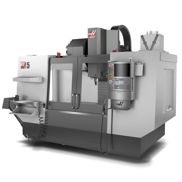
Vertical Milling Machine Haas VF-5/40TR
INTRODUCTION
A machining center is a computer-controlled machine tool used to perform a wide variety of operations and machining processes. These centers are increasingly widespread in the manufacturing world. This diffusion is due to the possibility of substantially increasing the production performance due to the automation of the production process which increases its precision and repeatability.
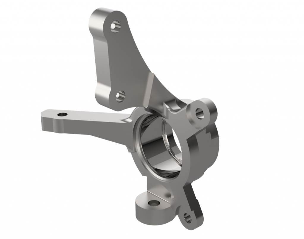
Example of a component machined by milling (grabcad.com)
WHAT IS A MACHINING CENTER
A machining center is a machine tool equipped with numerical control capable of autonomously performing in a repeatable and precise manner a wide range of operations described in a program in standard language (ISO 6983-1:2009) called G-code, which is usually expanded with specific commands from the manufacturer of the control and the machine tool itself. What distinguishes a machining center from a simple machine tool is also the versatility in the operations that can be performed. It is in fact possible to perform a wide range of operations (milling, drilling, turning, lapping, grinding, etc.) without the need to manipulate the component and transfer it from one machine tool to another when changing the type of process.
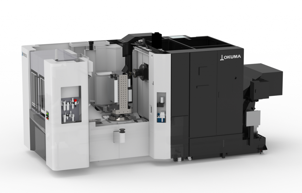
The Okuma MB-5000HII is a horizontal spindle milling center
GENERAL ANATOMY OF A MACHINING CENTER
The anatomy of a machining center can be very complex but there are elements in common to all machines that are necessary for operation.
THE MACHINE BED OR CHASSIS
The first component that is introduced is the chassis of the machine. This component is often overlooked but it contains many features that contribute to the good functioning of the machine tool. In fact, it has to:
- Perform the structural function of static support for the machine components. Secondly, it must guarantee rigidity to ensure minimal deformations arising from the inertia of the moving components and from the cutting forces during machining.
- Another important function performed by the chassis is to dampen as much as possible the vibrations coming from both the surrounding work environment and from the machine itself (vibrations produced by other machines, electric motors and other drives both internal and external to the machine).
- Reduce thermal deformations due to heat generated by machining and drives, but also by the surrounding environment.
Minimizing deformations and vibrations is of enormous practical importance as they can be the cause of defects in the manufactured component as non-respected tolerances or out-of-spec surface finishes.
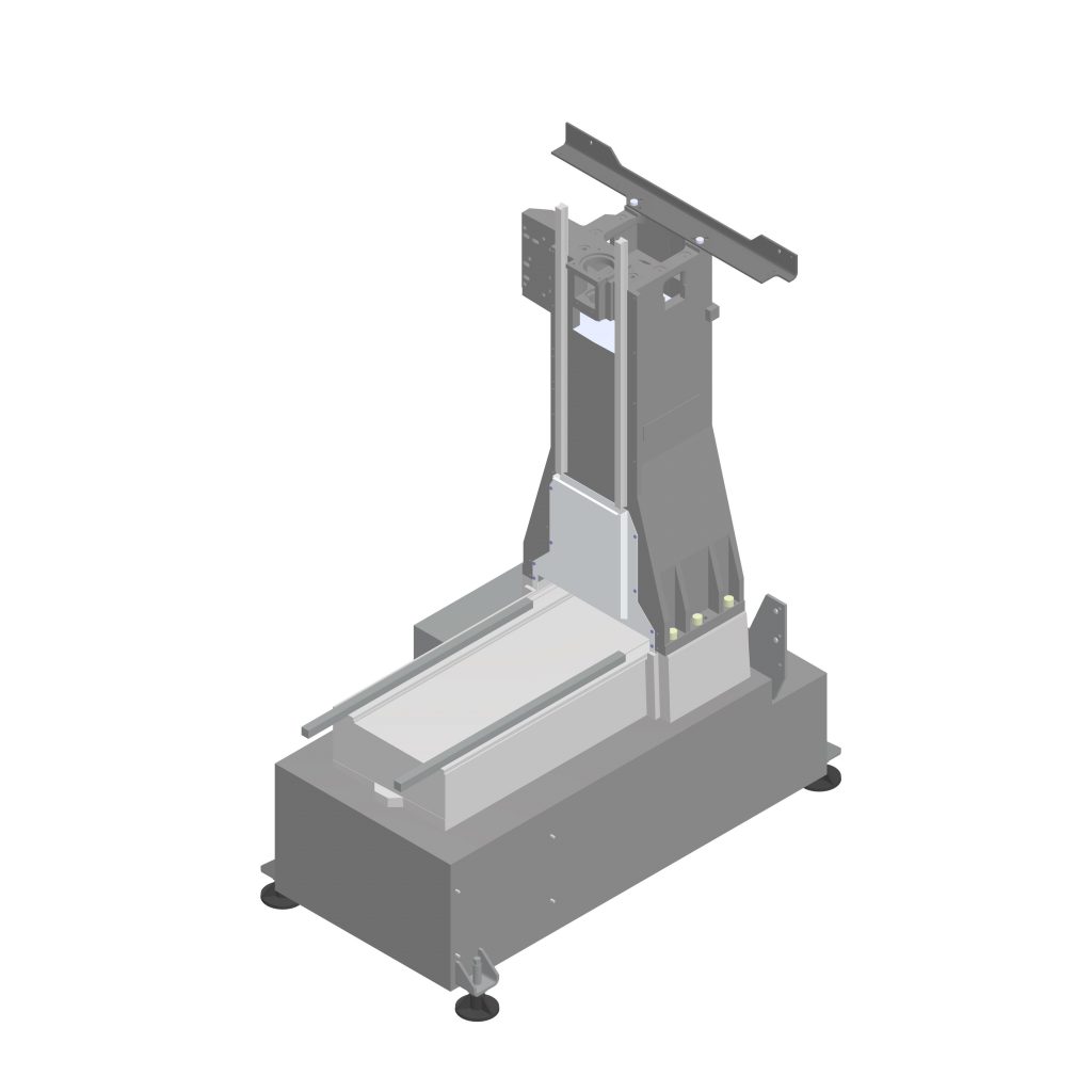
Example of a machining center chassis
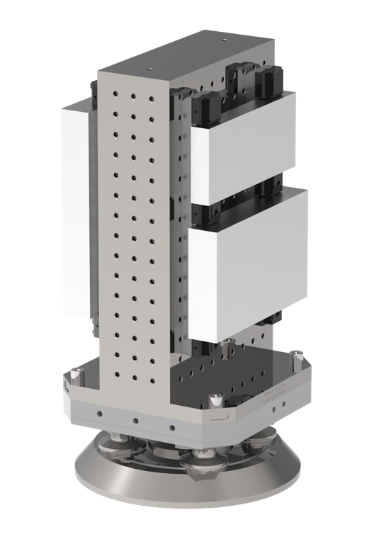
THE AXES
The machine axes are responsible for the motorized roto-translational movement (i.e. translation and rotation) between the tool and the blank.
The linear axes:
The axes that implement translational motion (i.e. along X, Y, Z) are in turn made up of various components:
- linear guide rails
- the table (or moving block) on which the spindle or blank is mounted
- the engine (non represented in the picture)
- the control screw (not represented in the picture), or the organ used to transmit motion between the motor and the moving block
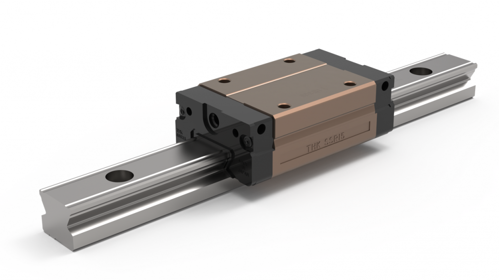
Example of a linear guide rail of a milling machine with moving block
Some of the most precise machines are equipped with linear motors that do not need to convert a rotary motion into a linear one. However, they are expensive and require adequate controls and heat dissipation systems. Currently they have a limited implementation (for example the YASDA YMC650+RT20).
As for the chassis, the guides and the moving blocks must also be designed in such a way as to be able to support the loads due to the process while reducing the deflections. In this case, high flexural and torsional rigidity are necessary to guarantee the precision in the movement and positioning of the parts.
The rotary axes:
These are the axes that implement rotary motion. They are conceived differently since the rotation is given directly by the electric motor without organs that convert the type of motion. A gearbox or transmission can eventually be inserted to regulate the torque and the rotational speed (e.g. a belt-pulley system).
THE SPINDLE
The spindle represents the beating heart of the machining center as it is responsible for providing power and transmitting it to the tool to remove material. There are different types of spindle but the most common are two:
- The belt-driven spindle, in which the motor is not coaxial with the tool's axis of rotation
- The spindle with integrated motor, in which the arrangement of the components is coaxial
Belt Driven Spindle
The first typology introduced is the one with belt drive. This type of architecture has several advantages:
- since the motor is separated from the spindle axis, there is the possibility of mounting a large motor, therefore, of accessing high power and torque
- it is an economic architecture as the components are of simple manufacture
- there is also the possibility of mounting a multi-speed gearbox, making the machine more versatile in terms of rotational speed and available torque
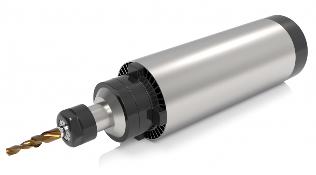
Spindle with integrated motor
The second type of spindle has an integrated motor. This type of architecture allows a direct connection between the motor and the spindle axis, removing the need for belts and bearings capable of withstanding high radial loads. However, other limitations are introduced, such as the need for a motor with a small diameter and consequently low torque and power expressed at the spindle due to the available space. The main advantage brought by this configuration is the possibility of reaching high rotational speeds without imposing high loads on the mechanical components.
Regarding the motor used to operate the spindles, the most common is the AC three-phase induction motor. The rotor is shrinked to the spindle shaft in the case of the integrated solution or to the pulley in the case of a belt. The important aspects that characterize the motor of a spindle are the torque/rotation speed and power/rotation speed curves. As in a classic electric motor, the maximum torque is reached at very low speeds and this decreases as the rotation speed increases. For this reason, it is important to take into account the availability of torque and power when designing the machining operation in order to identify the optimal region of cutting parameters to be used, such as cutting speed, feed rate and depth of cut.
THE TOOLHOLDER
The spindle alone is not sufficient to perform a machining operation, but a tool and an interface that can connect it to the spindle are needed. For this reason, so-called tool holders are used, which couples the spindle with the tool, that offers rigidity, centering precision and transmission of torque. For this purpose, there are various types of spindle/tool holder interface such as, for example, HSK (ISO 12164-1, DIN 69893), BT (JIS B 6339-2, MAS 403) etc.
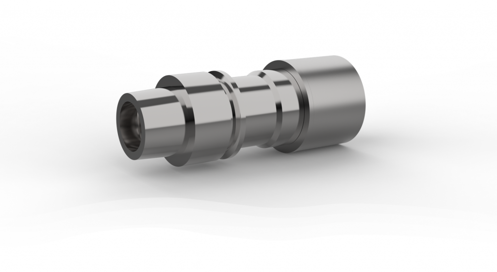
Tool holder with HSK interface (BIG KAISER HSK E32 MEGA13N 70 Tool Holder)
TOOL MAGAZINE
We now move on to present one of the most innovative parts introduced by CNC machining centers, namely the tool magazine with ATC (Automatic Tool Change) system. The magazine of these machines can be made in multiple architectures and dimensions. Consider that the capacity of a tool magazine can vary from a few units up to several hundreds. It is important to underline how the ATC system allows the automated replacement of the tool on the spindle in a precise and fast way.
There are mainly three types of ATC warehouse: drum, chain or robotic rack.
- The first one is shaped like a rotating drum with the tools arranged around its circumference.
- The second one instead includes chain and gear wheel systems with the tools always arranged in either a horizontal or vertical position.
- The third one finally includes shelving systems equipped with an automated mechanism capable of picking up the tool from the rack and bringing it to the spindle.
Automating this step ensures a significant gain in performance as the tool change is carried out in just a few seconds and guarantees a higher level of safety for the operator and for the tool itself as the former does not have to get close to the machine and the latter is handled much less.
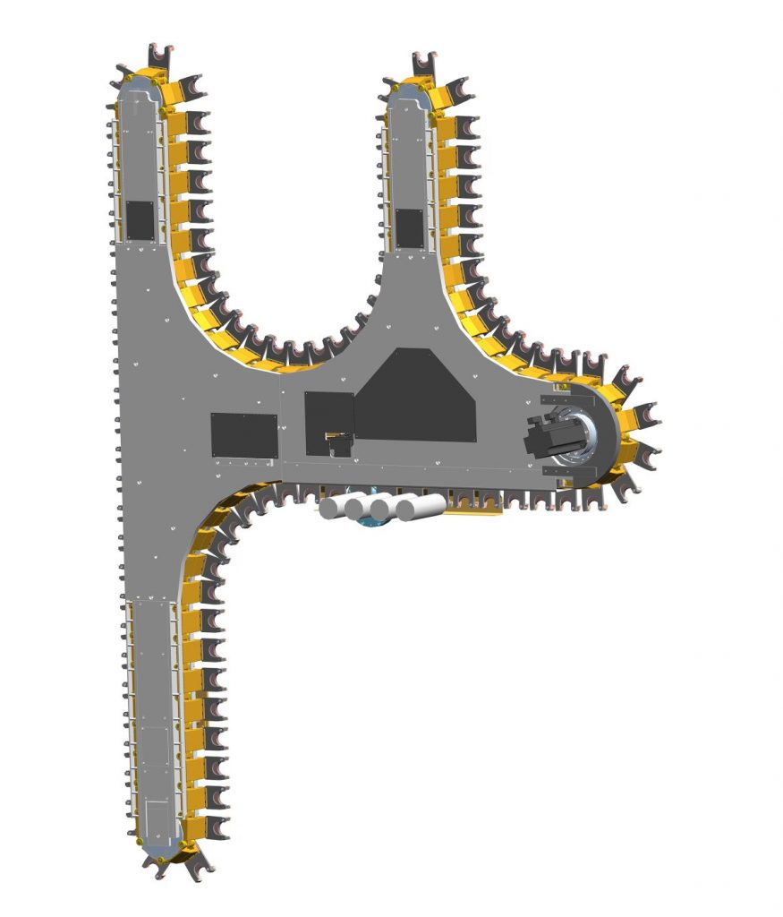
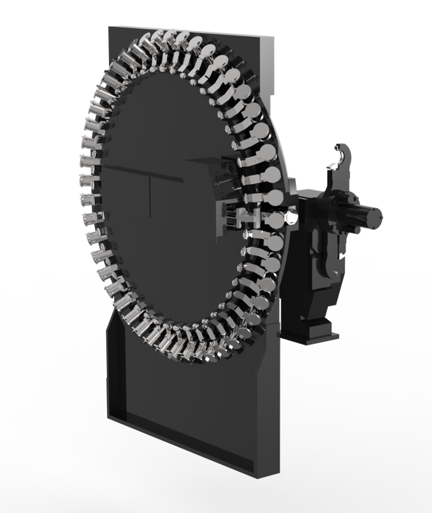
Examples of chain ATC (e.g. OKUMA GENOS M460V-5AX) and drum (e.g. HAAS UMC 750 SS)
Now that the general mechanical parts of the machine have been briefly introduced, we will introduce the type of control that allows the machining center to act automatically.
HOW DOES THE CONTROL OF MACHINING CENTERS WORK?
The control of a CNC (Computer Numerical Control) machine consists of three units: the NC unit, which provides the user interface and executes position control, the motor unit, and the driver unit. Strictly speaking, only the NC unit is called the CNC system. From a functional point of view, the CNC system is made up of the HMI or MMI (Human/Man Machine Interface) unit, the NCK (Numerical Control Kernel) unit, and the PLC (Programmable Logic Control) unit.
The HMI unit provides the interface between the NC and the user, executes the machine operation command, displays the machine status, and offers functions for editing the workpiece program.
The NCK unit, being the core of the CNC system, interprets the program and executes interpolation, position control, error compensation based on the interpreted program, controls the servo system, and determines the workpiece processing.
The PLC sequentially controls the tool change, spindle speed, workpiece change, input/output signal processing, and handles the machine's behavior control, except for servo control.
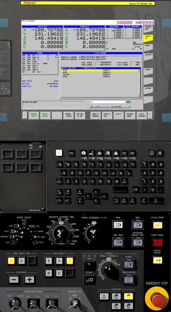
THE HMI
The HMI unit provides the interface (buttons, alarms, buzzers, screens, and switches) necessary for the user to communicate with the machine tools and vice versa. There are many types of user interfaces based on the CNC manufacturer's design concepts. The user interface functions are generally classified into five groups:
- Operative functions: these functions are the most frequently used and support the operation of the machine. Part of these functions is handled by the display that shows the machine’s status. For example, it shows the position, the distance to travel, the feed rate, the spindle speed, the block being executed, etc.
- Parameter setting functions: the operation of a CNC system is defined by parameters that influence its behavior, and they are classified into three types: machine parameters (used to set machine adjustments, the servo/spindle drive system, tool offsets, work coordinates, and axis travel limits), program parameters (must be set during the editing of the workpiece program, such as machine origin offsets), and customization parameters (used to adapt the machine to the user's needs, such as colors, language, etc.).
- Program Modification Functions: these functions can modify the workpiece program, which is a G-code based on the EIA/ISO standard. In practice, the user needs to know G/M codes and perform mathematical calculations to modify the program in G-code. Since mathematical calculations make it difficult to modify programs, more modern machines have introduced conversational programming systems, which are software that allows for the input of pre-programmed parametric operations.
- Monitoring and alarm functions: the CNC system informs the user of the machine's status, executes the programmed tasks, and reports the results to the user. These functions are essential when machine tools are running at high speed. They provide monitoring information such as alarm status, emergency recovery methods, PLC status, and the running ladder diagram.
- Service/Utility functions: many useful functions are provided to assist users. The DNC function for transmitting the workpiece program, which is modified externally to the CNC, the file service for copying internal parameters, and communication for connecting with computers.
HMI of YASDA YMC650+RT20
THE NCK
The main functions of the NCK unit are: interpreting ISO programs, calculating axis interpolation, serving as an acceleration/deceleration controller, and as a position controller.
- The interpreter plays the role of reading a program. Its reading occurs in ASCII blocks, and the interpreted data is stored in internal memory for the interpolator. In general, the NC issues commands related to the interpreted data, and the interpreter reads and interprets the next block while the command is being executed. In some cases, the speed at which commands are executed is higher than the speed at which they are read, potentially creating pauses between commands. To avoid these momentary stops during program execution, the blocks following the one being executed are read, and the processed commands are temporarily saved in a buffer while waiting to be executed (internal data buffer).
- The interpolator plays the role of sequentially reading the data from the internal data buffer, calculating the position and velocity per unit of time for each axis, and storing the result in a FIFO buffer for the acceleration/deceleration controller. In a numerical control system, four different types of interpolators can be used: linear, circular, parabolic, and spline. Depending on the application of the machine, the most suitable type is employed. The interpolator generates a pulse corresponding to the path data based on the type of trajectory and sends the pulse to the FIFO buffer. The number of pulses is determined based on the length of the path, and the pulse frequency is based on the speed.
- If position control were executed using the data generated by the interpolator, significant mechanical vibrations and shocks would occur every time the drive movements start and stop during each commanded feed. To prevent mechanical vibrations and shocks, the acceleration/deceleration control filter is applied before the interpolated data is sent to the position controller. This method is called the "acceleration/deceleration after-interpolation" method. There is also a method called "acceleration/deceleration before-interpolation", where acceleration/deceleration control is performed prior to interpolation.
- The data from the acceleration/deceleration controller is sent to a position controller, which operates based on the transmitted data over a constant time interval. Position control generally refers to a controller PID (Proportional Integral Derivative), which sends speed commands to the motor drive system to minimize the positional difference between the commanded position and the actual position detected by the encoder.
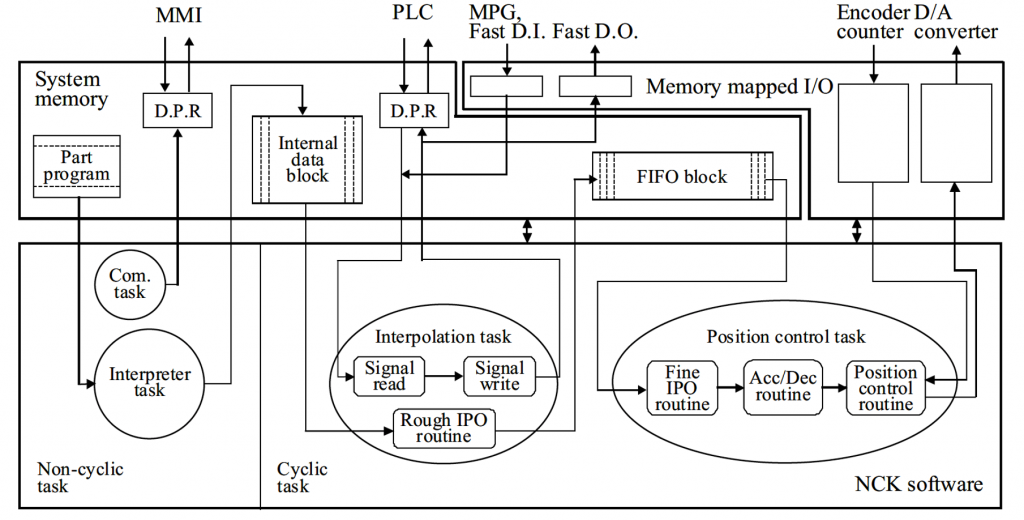
Logic schem of the NGK unit (“Theory and design of CNC systems”, Suh, S.H., Kang, S.K., Chung, D.H. and Stroud, I., 2008)
THE PLC
The PLC is used to execute the sequential control of actions in a CNC machine. In the past, logical control was performed using hardware made up of relays, counters, timers, and circuits. Therefore, it was considered a logic controller based on hardware.
However, modern PLC systems consist of various electrical devices, including microprocessors and memory, capable of performing logical operations, counting functions, timer functions, and arithmetic operations. Therefore, a PLC system can be defined as a logic controller based on software. The advantages of software-based PLC systems are as follows:
- Flexibility: the control logic can be modified by changing only a program.
- Scalability: the expansion of a system is possible by adding modules and modifying programs.
- Cost-effectiveness: cost reduction is possible due to shorter design times, high reliability, and easy maintenance.
- Miniaturization: the installation size is smaller compared to a relay control box.
- Reliability: the probability of failures due to a faulty contact decreases with the use of a semiconductor.
- Performance: advanced functions such as arithmetic operations and data modification are possible.
The hardware architecture of the PLC unit in an NC system includes a microprocessor, a system memory, a program memory, and an input/output module. As soon as the power is turned on, the system memory sets up the hardware environment of the PLC, and the program memory manages input/output, relays/timers/counters, and stores a user program and data to be interpreted by the microprocessor.
The PLC unit of a CNC system is similar to a generic PLC system, but there is an auxiliary controller that partially assists in the functions of the NCK unit. There are five different standardized PLC programming languages (IEC 1131-3):
- Ladder Diagrams (LD)
- Function Block Diagram (FBD)
- Sequential Function Chart (SFC)
- Structured Text (ST or STX)
- Instruction List (IL)
The most popular of the five is the LD thanks to its intuitive graphic design.
Example of programming in Ladder Logic language
CLASSIFICATION BASED ON PROCESSES TECHNOLOGY AND POSITION OF AXES
The main characteristic that is used to classify a machining center is the number of degrees of freedom available for machining, or the number of axes that can be operated by the machine. The most common types of machining centers are the following:
- 2 linear axes, where the interpolated axes are only 2
- 2 and a half linear axes, in which the interpolated axes are 2 while the third is moved only for positioning purposes
- 3 linear axes, where all 3 axes (X, Y and Z) are interpolated
- 4 axes, where the moving axes are 3 translation axes and one rotation axe
- 5 axes, in which the interpolated axes are 3 translations and 2 rotations, guaranteeing almost complete freedom of movement in space while remaining within the geometric and mobility limits of the machine axes (end of stroke, size of the equipment and of the rough material). The sixth axis is the rotation along he tool axis.
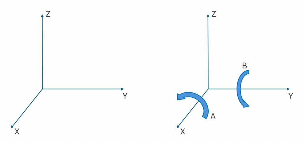
Degrees of freedom of a 3 and 5 axis machine
There are machining centers that have more than 5 machining axes. This means the possibility of performing a movement through redundant axes or multiple machining operations in parallel as in the case of multi-spindle machines (e.g. INDEX CNC-Mehrspindeldrehautomat MS40-8: Produktiver mit 8 Spindeln! – YouTube).
It is possible to make a further distinction in the vast panorama represented by machining centers. Based on the application of the machine tool, the main types of machining centers on the market are the following:
- 3-axis Vertical Milling Machine (VMC, Vertical Machining Center)
- 5-axis Vertical Milling Machine (VMC, Vertical Machining Center)
- 4-axis horizontal milling machine (HMC, Horizontal Machining Center)
- Bridge milling machine
- 2-axis lathe
- 3-axis lathe
- Multi-turret lathe
- Swiss lathe
3-AXIS VERTICAL MILLING MACHINE
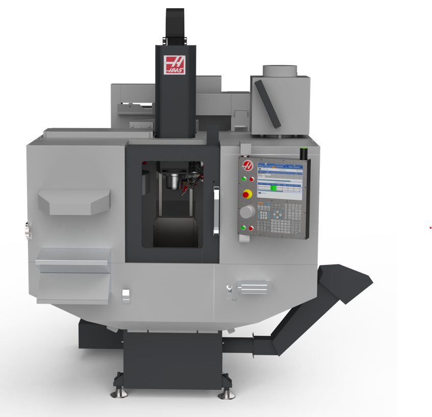
Example of a 3-axis vertical milling machine (Haas MiniMill)
A 3-axis VMC is characterized by the ability to move the X, Y and Z translation axes. It is called vertical because the rotation axis of the spindle is tipically in the vertical direction corresponding to the Z axis. These types of machines are very popular because they are very versatile, they give the possibility of creating shapes of any kind, as long as the geometry of the piece being machined does not have undercuts By design they have a more economical architecture than other more complex machines such as those with 4 or 5 axes.
The most general configuration of a 3-axis VMC consists of associating the translation along the X and Y axes to the worktable on which the workpiece is fixed, while the vertical translation Z is associated with the spindle axis. An example of this layout is the Haas MiniMill. There are also other configurations in which the X or Y axis or even both are associated with the spindle.
Application: Making simple to complex components without undercuts.
5-AXIS VERTICAL MILLING MACHINE
A 5-axis VMC is characterized by the ability to move the translation axes X, Y and Z and at the same time the rotation axes of which, in most cases, one is around the X or Y axis and one is around the Z axis but is housed on the table, allowing the piece to rotate on itself.
- Axis A → rotation around the X axis
- Axis B → rotation around the Y axis
- Axis C → rotation around the Z axis
These machining centers are the most versatile centers in absolute terms as they guarantee the greatest number of degrees of freedom for machining. They can work on complex geometries and those characterized by undercuts. Naturally, this flexibility affects both the cost of the machine, making this configuration one of the most expensive, and the difficulty of programming.
A common 5-axis VMC configuration associates one translational axis (X or Y) and two rotary axes to the machining table, while the other two linear axes are associated with the spindle. An example of this layout can be the Yasda YMC650+RT20. There are also other configurations in which for example both X and Y axes are responsible for moving the table etc.
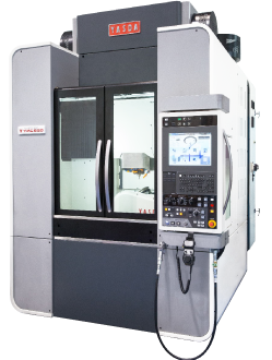
Example of a 5-axis vertical milling machine (Yasda YMC650+RT20)
It is useful to underline how the presence of rotation axes can contribute to the efficiency of a process that can be achieved also with a 3-axis milling machine. The possibility of varying the inclination between the tool and the piece makes it possible to adopt more efficient strategies than those implemented on a 3-axis machine. This involves both a reduction in production times and greater precision on the piece considering that with a 5-axis VMC it is possible to reduce the number of setups even when multiple faces of the component must be machined also in presence of undercuts.
Application: Machining of components with very complex geometries also characterized by undercuts with consequent reduction of the number of setups.
4-AXIS HORIZONTAL MILLING MACHINE
A 4-axis HMC is characterized by the ability to move the 3 translation axes X, Y and Z and at the same time also the rotation axes of the table. In this case, the machine is called horizontal because the rotation axis of the spindle is placed horizontally. According to the standard nomenclature, the Z axis is placed horizontally coherently with the spindle. An example of this type of machine is the Okuma MB-5000HII.
Example of a 4-axis horizontal milling machine (Okuma MB-5000HII)
The main advantage brought by an architecture like this is the possibility of working a large blank by blocking it on the table or smaller blanks by blocking them in a vice on a special fixture (tombstone, see figure). The horizontal position of the spindle facilitates the evacuation of the chip. Thanks to these peculiarities, workpiece holders called shoulders or squares (or tombstones) can be mounted on the table that can accommodate many blanks at the same time that can be worked in series, increasing the productivity of the machine.
Example of a tombstone
Application: Production of multiple components in series or alternatively large parts.
BRIDGE MILLING MACHINE
The portal milling machine is a milling machine (with three or five axes) with a particular configuration. In fact it was designed mainly for the production of large components to meet the need for long axis strokes. To this end, this type of milling machine is composed of two main elements which are the portal and the bed.
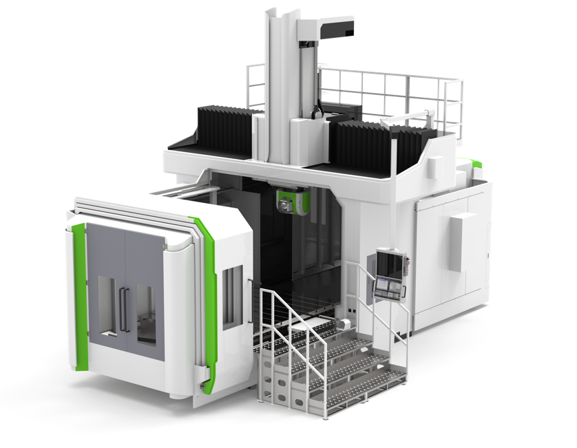
Example of a Gantry Milling Machine (Hartford HSA-423)
The portal (also called a bridge or gantry) is a double-column structure with a crosspiece that supports the spindle; the bed, on the other hand, constitutes the plane on which the component being machined is fixed. Given the considerable dimensions of the bed and the rough workpiece, it is not possible to house the rotary axes on the table since the mass to be rotated would be excessive and complex to manage. If the rotation axes are present, they must be mounted close to the spindle in order to give rotation to the tool. The portal structure also allows the milling machine to move around the machined component without too many space problems. There are then two variants of this milling machine: portal and mobile portal. While in the first case the translational motion along the longitudinal direction is given to the piece, in the second case, however, the translation in the same direction is given directly to the portal structure, which is housed on motorized guides. The transverse motion, however, in both typologies is given to the spindle that moves along the crosspiece of the portal. An example of a fixed portal milling machine is the Hartford HSA-423.
Application: Machining of components of considerable size and mass.
2-AXIS LATHE
The 2-axis lathe is the simplest type of CNC lathe on the market. The 2 translation axes in this case are the X axis and the Z axis. The first is perpendicular to the rotation axis of the piece, therefore, it moves the machining turret radially while the Z axis is parallel to the rotation axis and translates the turret in the longitudinal direction. An example of a 2 axis lathe is the Okuma GENOS L3000-E. This relatively simple configuration of the machine allows it to be economical but maintains high productivity.
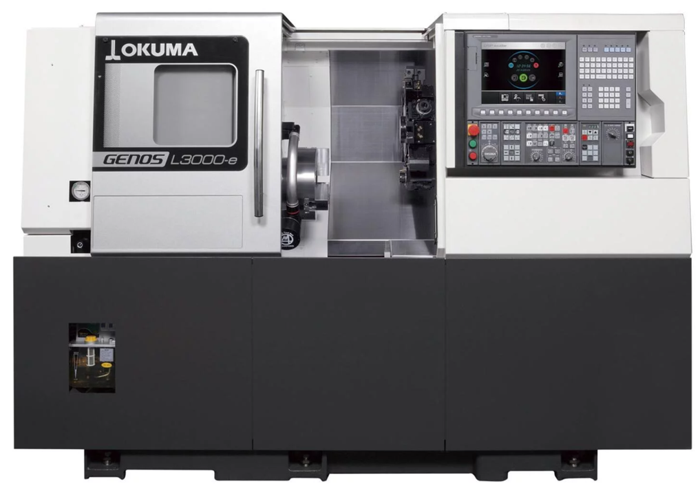
Example of a 2-axis lathe (Okuma GENOS L3000-E)
Application: Realization of axisymmetric components.
3-AXIS LATHE
The 3-axis lathe, compared to the 2-axis one, has a third axis called Y. The presence of this axis allows for complete movement capacity in the radial direction with respect to the rotation axis of the piece. In this way, it is possible to carry out not only simple turning and drilling operations but also milling operations. This is possible with motorized turrets and special tool holders equipped with transmission. They are able to give rotation to the cutter or tip, supplying power in order to remove material.
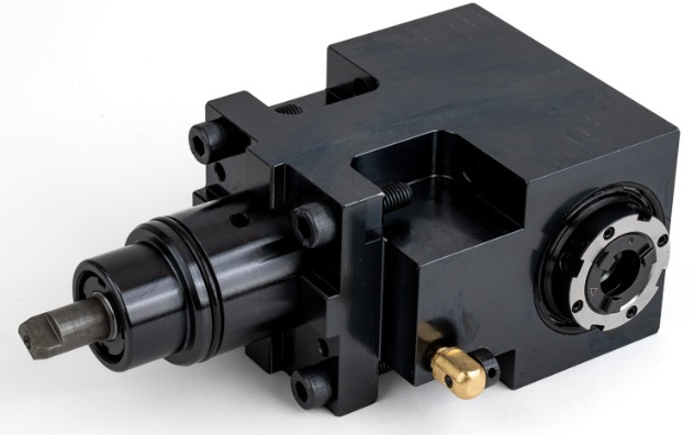
Example of a tool holder with transmission for a Haas BMT45 lathe model
An example of a 3-axis lathe is the Okuma GENOS L3000-E with the addition of the optional Y-axis. In this way, the machine becomes much more versatile and also allows for milling operations.
Application: Production of axisymmetric components or with simple prismatic geometries with the addition of features created by milling.
MULTI-TURRET LATHE
The multi-turret lathe has multiple tool turrets, each of which, in most cases, has 2 or 3 degrees of freedom with respect to the rough material and allows for multiple operations to be performed simultaneously. An example of a multi-turret lathe is the Okuma LT3000. The greatest advantage of using this configuration is increased productivity. The most competitive aspect of the machine is the ability to work in parallel and perform several operations simultaneously on the same piece. It is therefore suitable for use in high-volume production and situations where the investment can be amortized with the increased productivity. Typically, the products machined on these machines are produced in series that involve the production of large batches of the same component.
Example of the working area of a CMS TTL series multi-turret lathe
Application: Long, complex parts requiring large amounts of material removal. Small part machining where operations can be split between turrets to dramatically reduce cycle time.
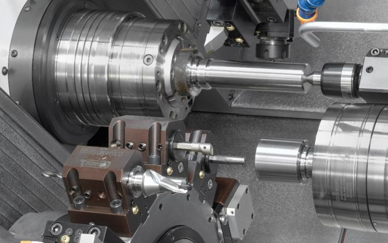
SWISS LATHE
The sliding headstock lathe is a special machine whose architecture differs from that of a classic lathe. The main peculiarity of a sliding headstock is that the feed motion, the longitudinal one, is no longer associated with the tool but with the rough material.
The Swiss lathe was born from the need to obtain multiple small components in series from single bars of long dimensions. The need therefore is to have the possibility of continuously supplying material to the work area without continuous clamping of shorter bars.
A Swiss lathe is schematized in the figure below. As you can see, the bar, which in this case is loaded from right to left, is pushed by the mobile headstock through a bushing called guide bush, whose function is to keep the system rigid. Once it enters the work area, the bar is machined by the tools that are fixed to the frame and that move along a radial direction.
An example of a sliding headstock lathe can be found in the Star SW-20.
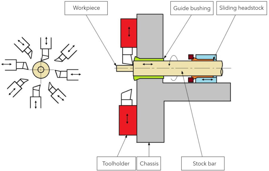
Schematic of a sliding headstock lathe
Application: Production of generally small components in large batches (screws, components for watches, etc.).
VERTICAL LATHE
This lathe works like a conventional lathe but the rotation axis of the piece is not horizontal but vertical. This configuration is mainly used for the production of heavy and large diameter components (e.g. train wheels) whose clamping on a horizontal vice would generate moments and shear stresses that the machine would not be able to support.
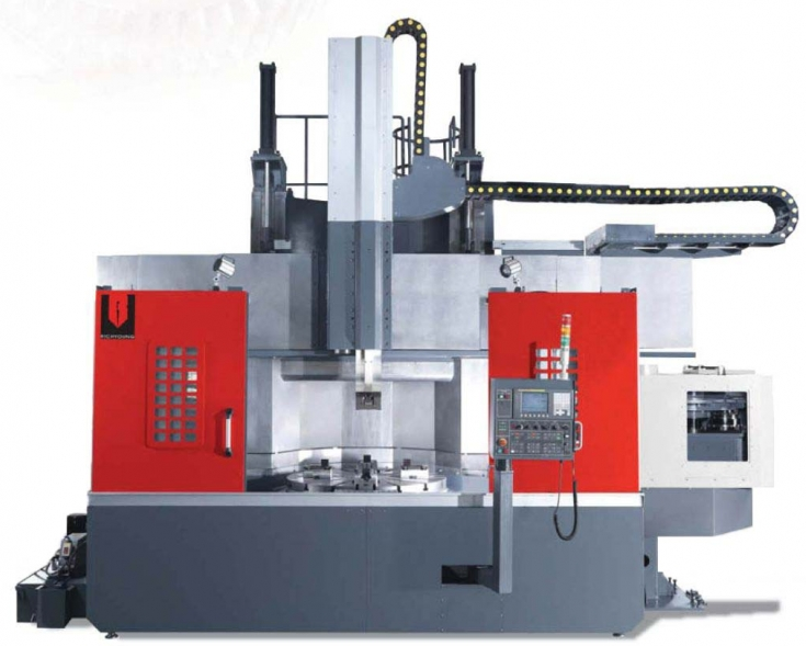
Example of a horizontal lathe (RIC-DV3000)
Application: Machining of components with large diameters and considerable mass.
MULTITASK MACHINING CENTER
A multitask machining center is a type of machine that can perform multiple operations without the need for a setup change. In general, a multifunctional machining center can perform both turning and milling operations without any repositioning of the blank or machine change between one operation and another.
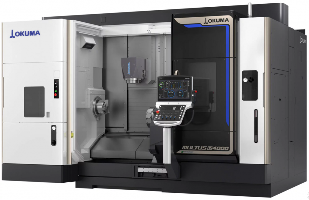
Example of a multitask center (Okuma MULTUS U4000)
There are multitask machining centers with different internal arrangements. For example, in the Okuma MULTUS U4000, there is a spindle with tip and tailstock with a horizontal rotation axis like in a traditional lathe, but there is also a spindle for milling. The peculiarity of this machine is that this second spindle can function both statically as a tool holder turret and as a real spindle and creates turn-milling or pure milling features.
Another arrangement could be that of the IBARMIA ZVH 55, in which the rotation for turning is given by the rotation of the table around the vertical axis, as happens for a vertical lathe.
The advantages brought by the adoption of this solution are multiple:
- Savings in terms of time and labor due to the absence of piece repositioning between one process and another, allowing the finished product to be obtained with a single set-up on a single machine
- Space saving, as one machine performs the functions that are traditionally associated with two different machines (lathe and milling machine)
- Improved accuracy, as single placement of the piece reduces sources of error.
- ACQUIRED SKILLS
You have acquired the following skills:
- Understanding the main functions of the components that make up a CNC machine
- Recognize the main types of CNC machines
- Recognize their main kinematic characteristics
- Make an initial choice of the machine configuration based on the pieces to machine

USEFUL CONTACTS, LINKS AND DOWNLOADS
Contacts
- For students:
Prof. Annoni Massimiliano, Politecnico di Milano: massimiliano.annoni@polimi.it - For educators:
Prof. Annoni Massimiliano, Politecnico di Milano: massimiliano.annoni@polimi.it - For companies:
Prof. Annoni Massimiliano, Politecnico di Milano: massimiliano.annoni@polimi.it
Ufficio marketing, Celada Spa: marketing@celadagroup.com
Useful Links
- LEARNING TIME: -- min.