
Using the spindle torque and power curve to choose cutting parameters
PREREQUISITES
- Basic knowledge of CNC
- Basic knowledge of milling processes
- Basic knowledge of CAD/CAM software
- LEARNING TIME: 40 min.
OBJECTIVES
- Choose the appropriate tool diameter and rotational speed for the machining considering the torque and power that can be delivered by the spindle
- Perform useful calculations to define the cutting parameters as a function of the chosen position in the spindle characteristic curve
ADVANCE QUESTIONS
Do you know that the machine may fail if you don't choose the cutting parameters correctly considering the torque and power that can be delivered by the spindle?
Do you know that it is not enough that the tool holder on the machine can fit a certain tool diameter to be sure that the machine will be able to withstand the torques and powers that are generated in machining?
Did you know that machining centers are specially designed to work under specific conditions? In other words, a machine suitable for precision machining is not suitable for standard machining
Do you know how to calculate the forces, torques and powers generated in machining? It is useful for choosing tools!
Choice of cutting speeds
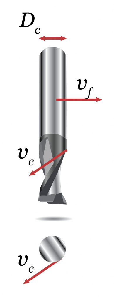
Rappresentazione delle velocità caratteristiche di un processo di fresatura.
- Dc dipende dalla geometria del pezzo da lavorare (v. “Selezione dei parametri di taglio nelle aree critiche del percorso utensile (raccordi)”).
- vc is recommended by tool manufacturers depending on the target material-tool material torque so it can be considered constant.
- Dc dipende dalla geometria del pezzo da lavorare (v. “Selezione dei parametri di taglio nelle aree critiche del percorso utensile (raccordi)”).
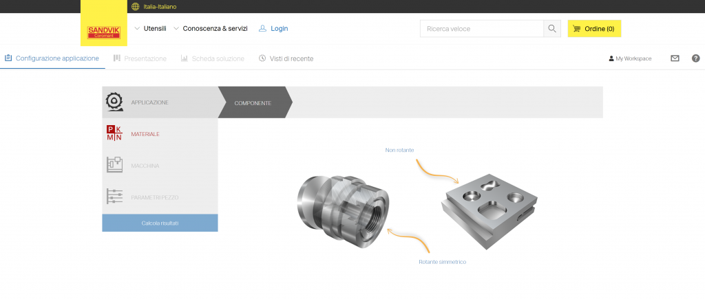
Interfaccia di CoroPlus Tool Guide, software online per la scelta dei parametri di taglio (Sandvik Coromat).
SELECTION OF TOOL DIAMETER
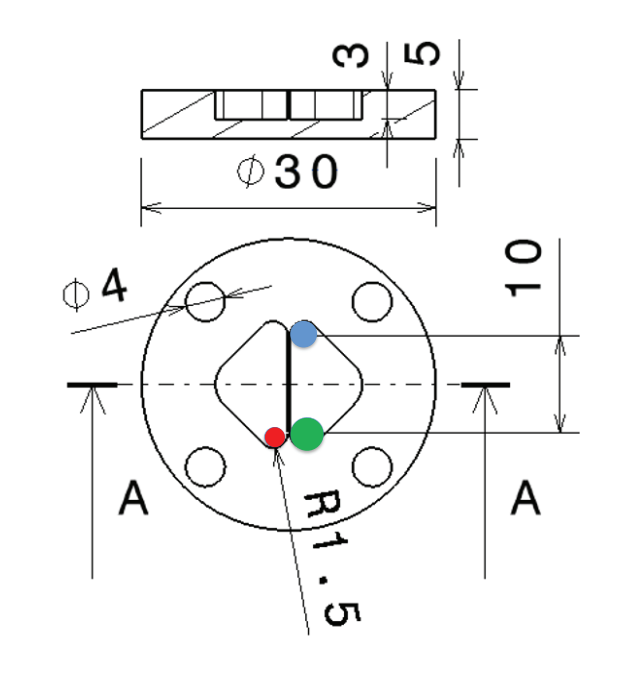
Esempio di tasche con spigoli raccordati a 1.5 mm.
Possible tool diameters:
- Dc1 = 2 mm
- Dc2 = 2.8 mm
- Dc3 = 4 mm
La terza fresa è chiaramente non adatta, ma potremmo sceglierne una delle altre due. Dc dipende dalla geometria da realizzare. In generale, è meglio usare utensili relativamente grandi in quanto sono più rigidi, ma i raccordi nel pezzo limitano il raggio utensile (v. “Come selezionare un utensile usando un catalogo online”).
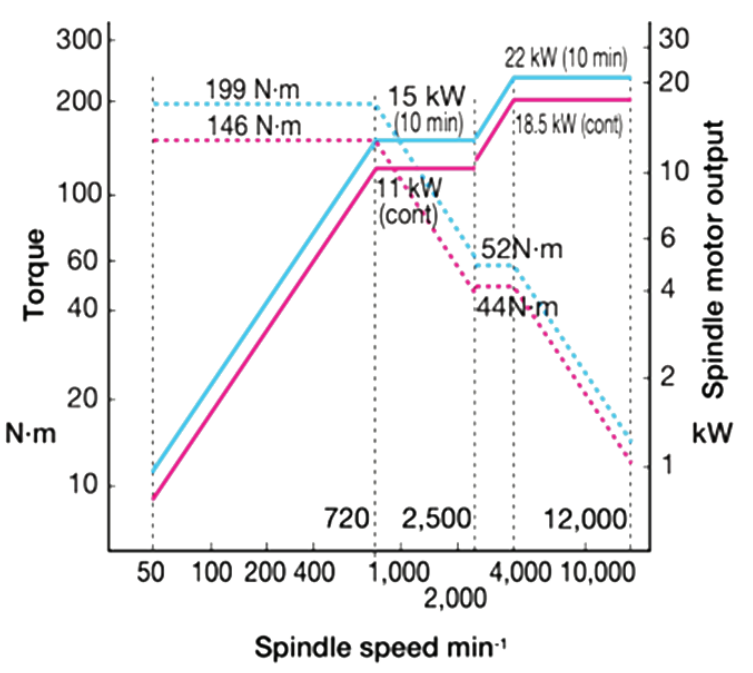
USE OF SPINDLE TORQUE AND POWER DIAGRAM FOR PARAMETER SELECTION
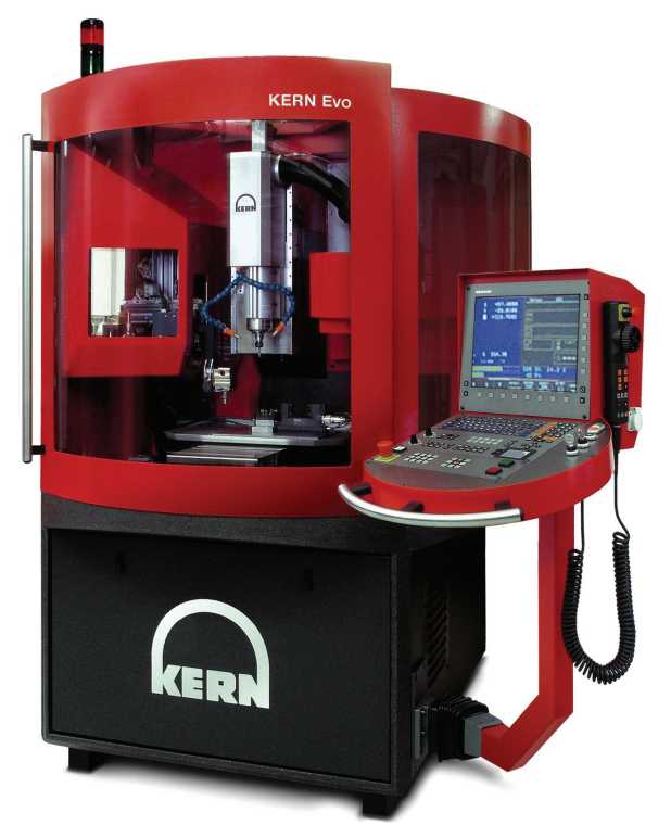
Centro di lavoro Kern Evo.
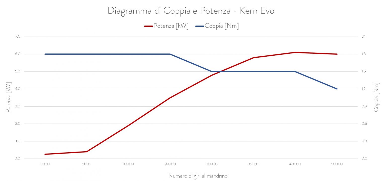
This diagram is the characteristic curve of the spindle, which has a fundamental importance for choosing the tool and process parameters. The first thing to note is that the torque and power performance stated in the machine datasheet refers to a certain RPM range.
In fact, it can be seen that maximum power is provided only above 40,000 rpm.
This means that the machine spindle is suitable for fast turning.
INTERAZIONE TRA DIAMETRO DELL'UTENSILE E VELOCITÀ DI TAGLIO
v_c=\frac{\pi \cdot D_\mathrm{c} \cdot n}{1000}
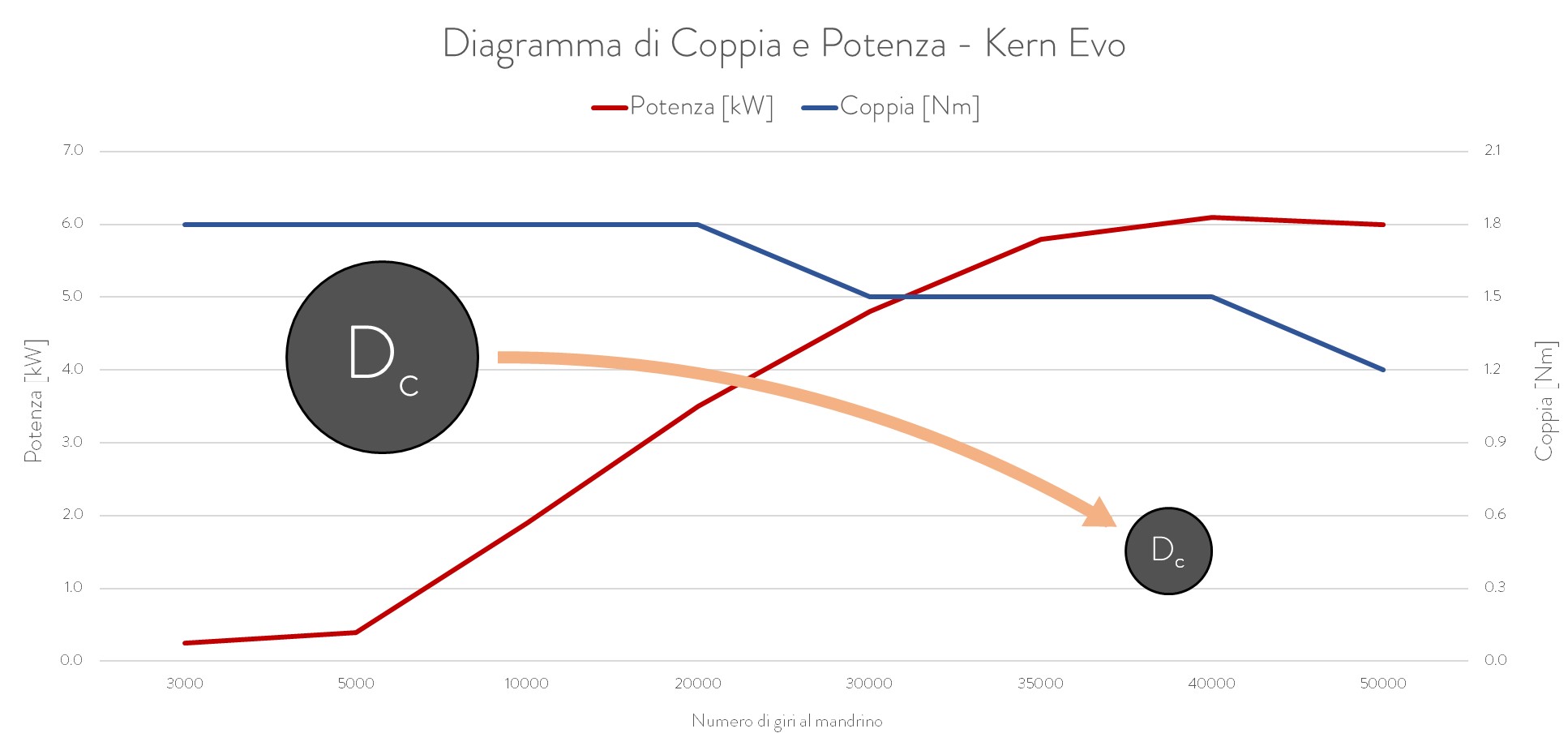
Variazione del punto di utilizzo della macchina in funzione del diametro di taglio.
FEED RATE AND MATERIAL REMOVAL RATE (MICRO MILLING)
v_\mathrm{f} = n\cdot f_\mathrm{z}\cdot Z
Z vale tipicamente 2 in microfresatura e n tende ad essere elevato per sfruttare meglio il mandrino, inoltre fz non può essere troppo piccolo per evitare il ricalcamento (minimum chip thickness effect).Profondità di passate assiale ap, radiale ae e velocità di avanzamento vf.
The feed rate increases: this means that vf tends to be high in micromilling. For this reason, micro-milling centers must have good performance in terms of maximum feed rate.
MRR = v_\mathrm{f}\cdot a_\mathrm{p} \cdot a_\mathrm{e}
Il Material Removal Rate (MRR), o Volume di truciolo asportato (Q) è limitato da ap e ae che sono piccoli in quanto legati alle dimensioni dell’utensile.
Per massimizzare l’MRR, abbiamo già vf, ma anche la profondità di taglio deve essere considerata. ae è limitata per preservare l’integrità dell’utensile (v. “Selezione dei parametri di taglio nelle aree critiche del percorso utensile (raccordi)“). ap invece può essere aumentata secondo le indicazioni dell’utensiliere e le nuove strategie di fresatura trocoidali (bassa ae e alta ap), che sono state inventate per la fresatura ad alta velocità e la microfresatura.
STANDARD MILLING
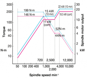
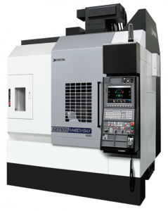
Diagramma caratteristico dell’Okuma Genos M460V.
In questo nugget, consideriamo quello che accade nelle traiettorie rettilinee. Considereremo quanto accade nelle curve nel prossimo nugget. ae gioca un ruolo sullo spessore massimo del truciolo hex tramite l’angolo di impegno della fresa. hex può essere usato per calcolare la forza di taglio massima secondo il metodo della pressione di taglio. L’angolo di spoglia frontale (ɣ0) gioca un ruolo importante nella pressione di taglio.
Come noto, quando ɣ0 aumenta, l’azione di taglio richiede una forza minore. In qualche caso, un valore rappresentativo medio della forza di taglio deve essere calcolato per un certo angolo di impegno della fresa. Lo spessore di truciolo medio hm può essere calcolato come indicato di seguito. hm può essere usato per calcolare la corrispondente pressione di taglio e forza di taglio.
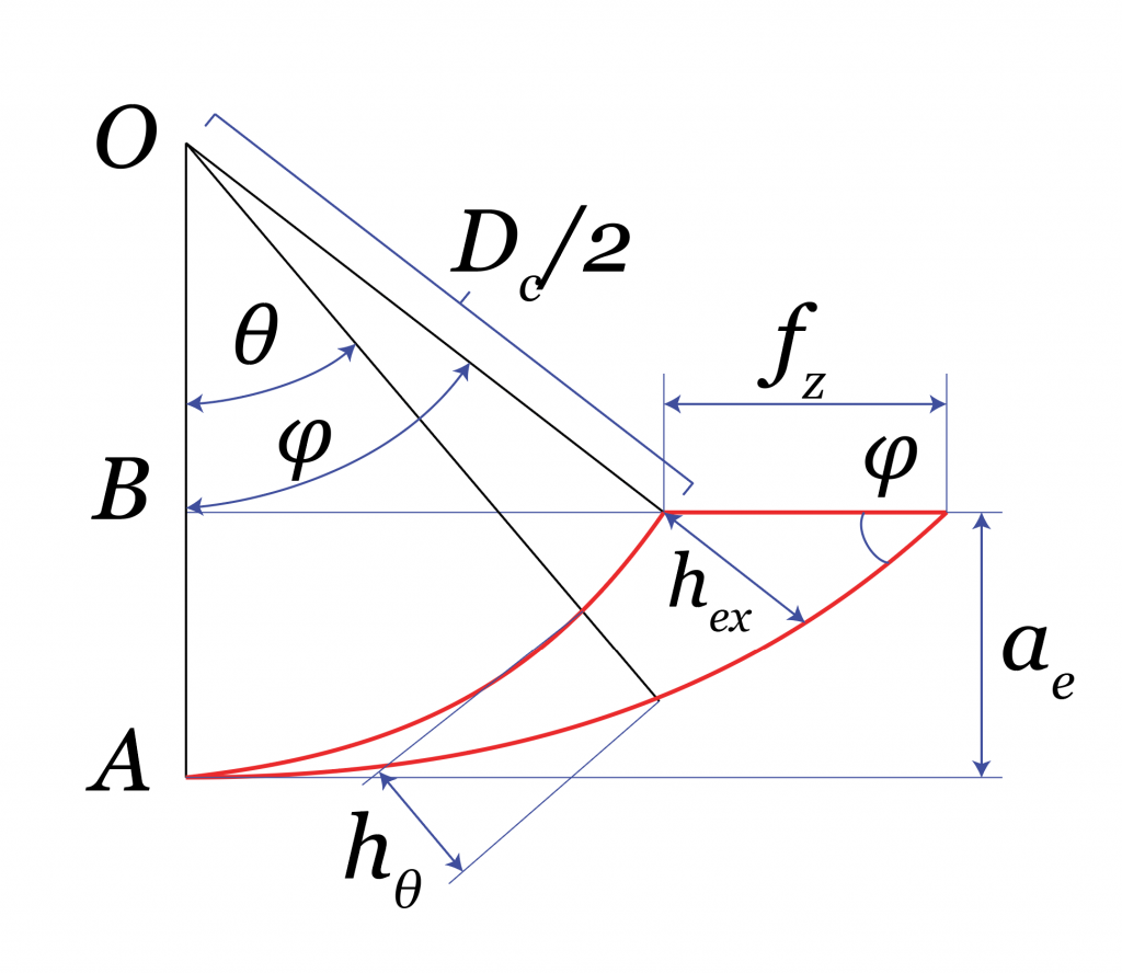
Scheme for calculating the average and maximum chip thickness.
Tool engagement angle:
cos(\varphi) = \frac{\frac{D_\mathrm{{c}}}{2}-a_\mathrm{e}}{\frac{D_\mathrm{{c}}}{2} } = \frac{D_\mathrm{{c}}-2a_\mathrm{e}}{D_\mathrm{{c}}} = 1 – \frac{2a_\mathrm{e}}{D_\mathrm{c}}
Approach to maximum chip thickness:
h_\mathrm{{ex}} = f_z sin(\varphi)
k_\mathrm{{c,ex}} = k_\mathrm{{c1}}h_\mathrm{{ex}}^{-x}(1-\frac{\gamma_0}{100})
F_\mathrm{{c,ex}} = k_\mathrm{{c,ex}}A_\mathrm{D} = k_\mathrm{{c,ex}}h_\mathrm{{ex}}a_\mathrm{p}
Approach to average chip thickness:
h_\mathrm{m}=\frac{2f_\mathrm{z}a_\mathrm{e}}{\varphi D_\mathrm{{c}}}
k_\mathrm{{c,m}} = k_\mathrm{{c1}}h_\mathrm{{m}}^{-x}(1-\frac{\gamma_0}{100})
F_\mathrm{{c,m}} = k_\mathrm{{c,m}}A_\mathrm{D} = k_\mathrm{{c,m}}h_\mathrm{m}a_\mathrm{p}
kc1: Reference cutting pressure (N/mm2)
x: Tool material coefficient (e.g. x = 0,25)
kre = 90° (flat-end mill)
Notes:
- Express ɣ 0 to decimal values in the kc,ex
- In generale usiamo lo spessore medio di truciolo per calcolare la forza valido anche per valori di φ > 90°, anche se in quel caso sottostimerebbe il valore dello spessore massimo del truciolo. Nel nostro caso, abbiamo φ < 90°, così possiamo usare hex espresso dalla formula indicata per essere conservativi. In questo modo, possiamo calcolare lo spessore massimo di truciolo e la forza massima.
CUTTING TORQUE, POWER AND TOOL DEFLECTION
Considering that only one cutting edge is engaged at a time, we can use simple formulas to calculate torque and cutting power. As done previously, we refer to the average chip thickness and the maximum chip thickness hm and hex.
M_\mathrm{{c,m}} = F_\mathrm{{c,m}}\frac{D_\mathrm{c}}{2}
M_\mathrm{{c,ex}} = F_\mathrm{{c,ex}}\frac{D_\mathrm{c}}{2}
P_\mathrm{c} = F_\mathrm{c}v_\mathrm{c}*
Moment of inertia of a circular section (we model the cutter as a cylinder; in this way we overestimate J):
J = \frac{\pi D_\mathrm{c}^4}{64}
The tool deflection which is expressed in the following equation plays a role in the accuracy of the part.
d = \frac{F_\mathrm{c}L^3}{3EJ}**
*Valid formula for an engaged cutting edge
**L is the cantilever length (we consider the cutter as a fixed beam)
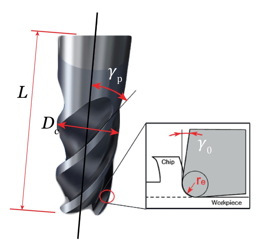
Schema delle grandezze caratteristiche di una fresa: diametro di taglio Dc, lunghezza a sbalzo L, angolo d’elica ɣp, angolo di spoglia frontale ɣ0 e raggio di punta dello spigolo re.
- ACQUIRED SKILLS
You have acquired the following skills:
- Choose the cutting parameters taking into account the torque and power curve of the machine spindle.

USEFUL CONTACTS, LINKS AND DOWNLOADS
Contacts
- For students:
Prof. Massimiliano Annoni, Politecnico di Milano: massimiliano.annoni@polimi.it - For educators:
Prof. Massimiliano Annoni, Politecnico di Milano: massimiliano.annoni@polimi.it - For companies:
Prof. Massimiliano Annoni, Politecnico di Milano: massimiliano.annoni@polimi.it
- LEARNING TIME: -- min.